Unmanned aerial vehicle for logistical delivery

a technology of aerial vehicles and logistical delivery, applied in the direction of vertical landing/take-off aircraft, transportation and packaging, gliders, etc., can solve the problems of insufficient safety, insufficient safety, and inability to meet the needs of logistics distribution, and achieve the effect of reliable, effective and economical

Inactive Publication Date: 2006-06-13
US SEC THE NAVY CHIEF OF NAVAL RES OFFICE OF COUNSEL ATTN CODE OOCIP
View PDF46 Cites 66 Cited by
  • Summary
  • Abstract
  • Description
  • Claims
  • Application Information

AI Technical Summary

Benefits of technology

[0008]In view of the foregoing, it is an object of the present invention to provide a methodology for effecting military logistical payload delivery in a safe, reliable, effective and economical manner.
[0013]The present invention's system, which the inventors style the “Advanced Logistics Delivery System” (acronymously designated “ALDS”), supports the need to deliver supplies to dispersed U.S. special operational units located in rear offshore locations, and supports the need to do so reliably, on demand, twenty-fours hours a day and independently of environmental conditions. Of primary import to inventive practice, the inventive ALDS uses a low cost, disposable, unmanned, autonomous and un-powered aerial vehicle that can be operated off of a variety of launch platforms. It is anticipated that, as typically embodied if adopted by the U.S. Navy, the inventive ALDS will be capable of meeting long distance delivery goals (e.g., delivering up to 1,000 pounds or more of payload over a distance of up to 200 nautical miles) at low cost.
[0015]For most applications, the present invention's unmanned payload-carrying vehicle includes a body and a pair of wings. The inventive glider's body includes a nose, a fuselage (to be utilized for carrying a payload) and an empennage (i.e., a tail). The wings include port and starboard aerodynamic surfaces and are characterized by port and starboard airfoils. The inventive glider represents a unique carrier that lends itself to inexpensive construction and is thus disposable on landing. The inventive glider preferably includes a low-cost, rigid, composite sandwich construction for the fuselage and empennage, and a low-cost energy-absorbent composite foam construction for the nose. The fuselage structure, the empennage structure and the nose structure are each characterized by adequate aerodynamic strength and rigidity. The inventive glider's wings, which are initially stowed inside or adjacent to the fuselage, deploy to full extension (e.g., full inflation or full unfolding) when, post launch, the glider reaches a predetermined elevation (e.g., apogee) and position (e.g., geographic location). The stiffened inflatable wings are deployed “on demand” while in flight at the selected elevation pursuant to preprogrammed criteria.
[0017]In contrast, the present invention's ALDS implements unmanned aero-glide, un-powered, autonomous payload vehicles that can carry smaller amounts of supplies for delivery to Spec Ops troops in the field. The inventive supply approach is essentially characterized by low risk to personnel because they will tend to be out of harm's way. The inventive system can be practiced at a fraction of the cost that would obtain if the delivery vehicle were manned. The inventive ALDS is based on an un-powered, expendable delivery UAV (unmanned aerial vehicle) that is noiseless and hence more suitable for covert operations than is a powered vehicle.

Problems solved by technology

These methods of delivery, generally encompassed by what is referred to as the “iron mountain” approach, are ponderous.
The iron mountain approach to cargo transport is constantly at risk of attack, is inherently expensive and requires considerable distribution logistics.
High altitude delivery significantly reduces but does not eliminate aircraft vulnerability.
Moreover, considerable cost is associated with dedicated manned missions of this kind.

Method used


Image

  • Unmanned aerial vehicle for logistical delivery
  • Unmanned aerial vehicle for logistical delivery
  • Unmanned aerial vehicle for logistical delivery

Examples


Embodiment Construction

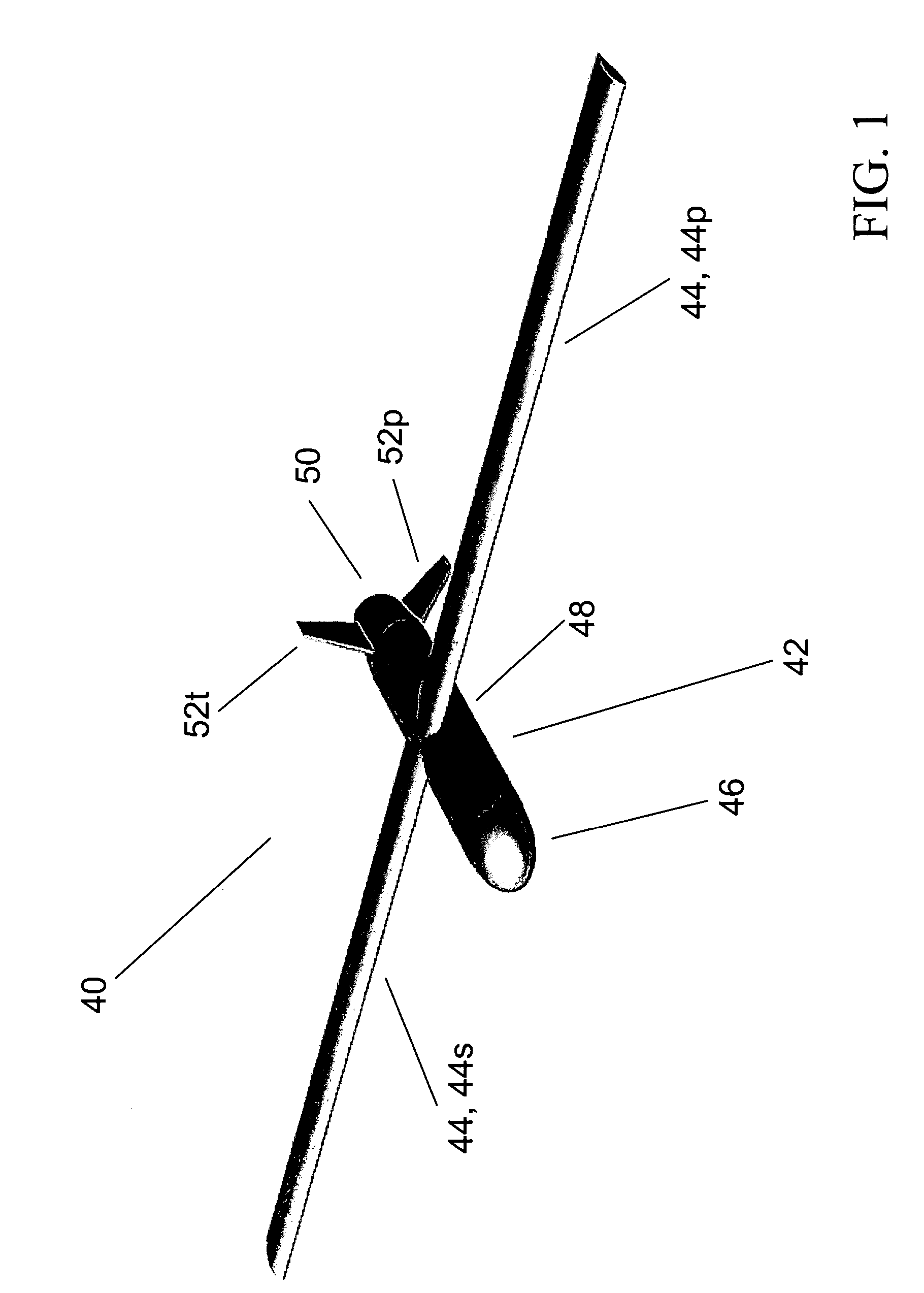
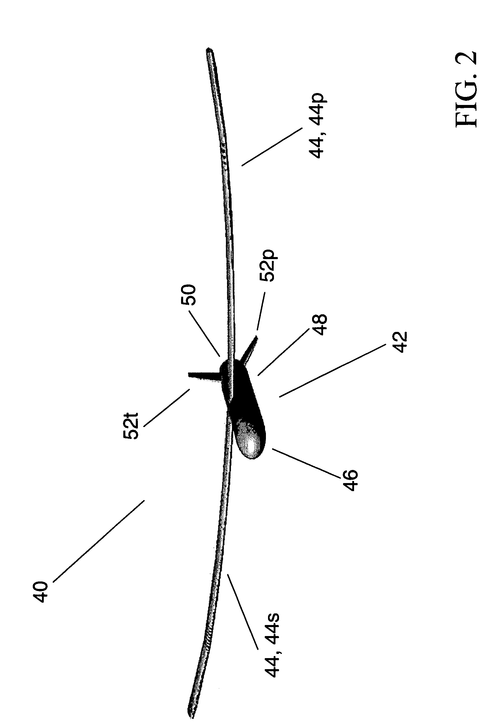
[0052]Referring now to FIG. 1 through FIG. 3, inventive glider 40 is an unmanned, disposable, mass-producible, structural vehicle. At least substantially made of composite materials, inventive glider 40 is relatively lightweight, yet is sufficiently robust to withstand loads associated with launch (especially, rocket launch), flight, landing and carrying cargo. Inventive glider 40 is sufficiently versatile to accommodate different launch methodologies. It can support two-hundred-mile military logistics missions, and allows for range variations.

[0053]Inventive glider 40 includes a body 42 and a pair of wings (airfoils) 44, viz., port wing 44p and starboard wing 44s. Body 42 includes three body sections, viz., a nose 46, a fuselage 48 and a tail 50. Fuselage 48 is attached flush to rounded nose 46 at the front end 74 of fuselage 48, and is attached flush to tail 50 at the back end 76 of fuselage 48. Tail 50, the entire empennage assembly, includes casing 96 and three stabilizers 52p, ...


PUM


Abstract

A hollow elliptical-cylindrical hull conformingly houses a hollow rectangular-prismatic cabin whereby the four longitudinal parallel outside edges of the latter make contact with the inside surface of the former. The fully constructed aircraft (either non-powered or powered) includes the integral hull-plus-cabin structure along with nose, tail and airfoil structures that are coupled therewith. The cabin conformingly accommodates hollow rectangular-prismatic modules useful for cargo storage. While the nose and / or tail structure is uncoupled from the integral hull-plus-cabin structure, the modules are inserted into the cabin and the cabin is sealed. The aircraft is lifted (e.g., via airplane, helicopter, rocket or balloon) to a particular elevation and released, whereupon the two wings fully emerge and the aircraft effects controlled flight until reaching its destination. After landing, the nose and / or tail structure is uncoupled from the integral hull-plus-cabin structure, the cabin is unsealed, and the modules are removed from the cabin.

Description

CROSS-REFERENCE TO RELATED APPLICATIONS[0001]This application claims the benefit of U.S. Provisional Application Ser. No. 60 / 479,847, filed 20 Jun. 2003, inventors David W. Byers, Gary A. Hall, Graham D. Hunter, Colen G. Kennell, Aleksander B. Macander, Judah H. Milgram and Jason D. Strickland, entitled “Unmanned Aerial Vehicle for Logistical Delivery,” incorporated herein by reference.STATEMENT OF GOVERNMENT INTEREST[0002]The invention described herein may be manufactured and used by or for the Government of the United States of America for governmental purposes without the payment of any royalties thereon or therefor.BACKGROUND OF THE INVENTION[0003]The present invention relates to unmanned vehicles and to methods and systems utilizing unmanned vehicles, more particularly to same involving air transportation.[0004]The United States Navy desires that its forces have a logistics sustainment projection power of up to 200 nautical miles, which is the typical distance from a ship launc...

Claims


Application Information

Patent Timeline
Patent Type & Authority Patents(United States)
IPC IPC(8): B64C1/00B64C1/06B64C1/22B64C3/58B64C29/02B64C31/02B64C39/02B64D5/00
CPCB64C1/061B64C1/22B64C3/58B64C29/02B64C31/02B64C39/024B64D5/00B64C1/068B64C2201/187B64C2201/082B64C2201/084B64C2201/105B64C2201/128B64C2201/141B64C2201/185B64U70/20B64U70/70B64U2201/10B64U70/60B64U70/83B64U2101/69B64U10/25B64U30/10B64U50/15B64U30/12B64U2101/60
Inventor BYERS, DAVID W.HALL, GARY A.HUNTER, GRAHAM D.KENNELL, COLEN G.MACANDER, ALEKSANDER B.MILGRAM, JUDAH H.STRICKLAND, JASON D.
Owner US SEC THE NAVY CHIEF OF NAVAL RES OFFICE OF COUNSEL ATTN CODE OOCIP
Why Eureka
Try Eureka