Projector, network system including projector, and method of controlling projector on network system

Active Publication Date: 2006-06-13
MITSUBISHI ELECTRIC CORP
View PDF20 Cites 16 Cited by
  • Summary
  • Abstract
  • Description
  • Claims
  • Application Information

AI Technical Summary

Benefits of technology

[0005]It is an object of the present invention to provide a projector that can make it easy to construct a netw

Problems solved by technology

However, there are many users of projectors who are not acquainted with a

Method used


Image

  • Projector, network system including projector, and method of controlling projector on network system
  • Projector, network system including projector, and method of controlling projector on network system
  • Projector, network system including projector, and method of controlling projector on network system

Examples


Example

First Embodiment

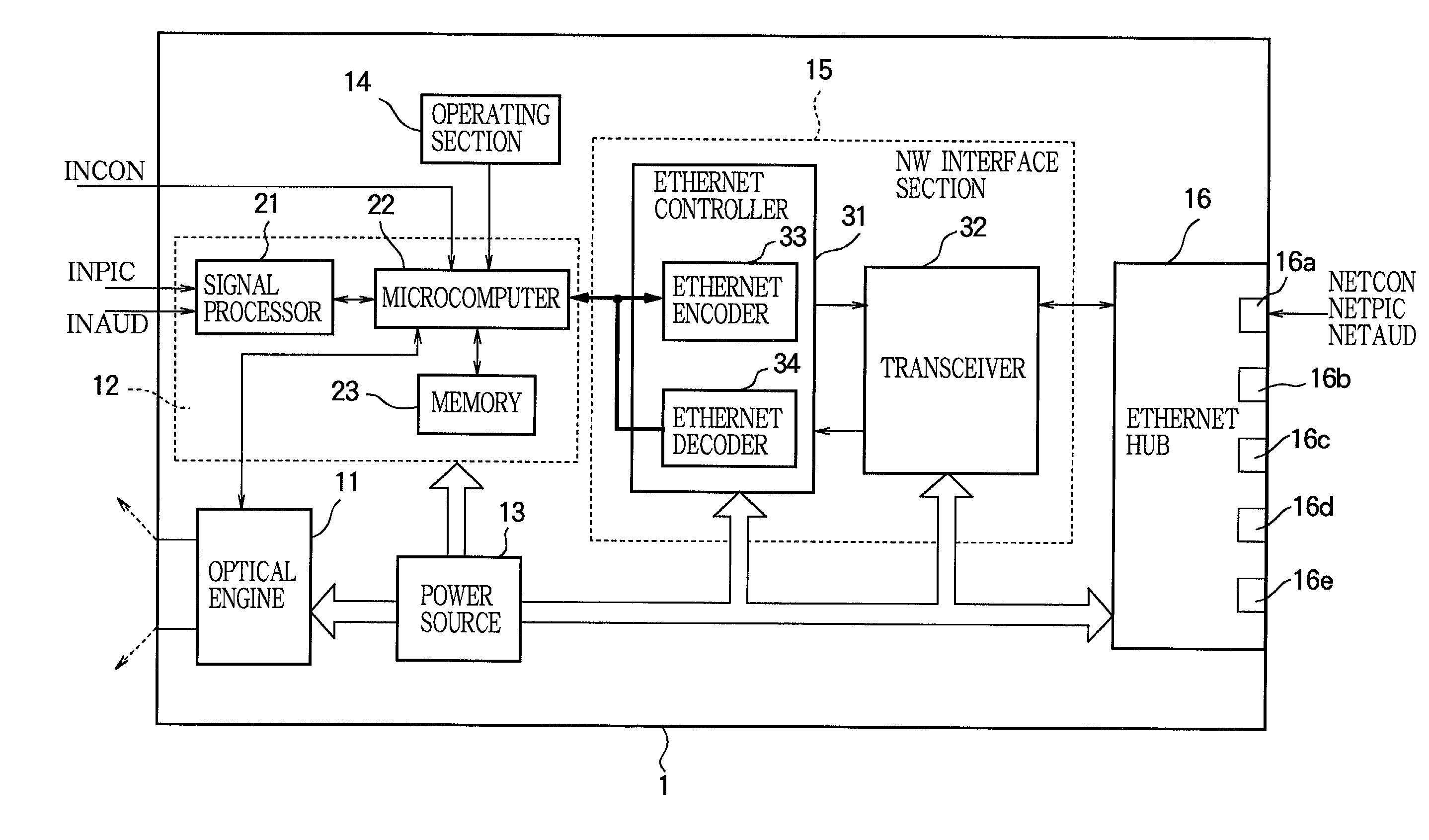
[0034]FIG. 1 is a block diagram schematically showing a projector 1 according to the first embodiment of the present invention.

[0035]As shown in FIG. 1, the projector 1 according to the first embodiment comprises an optical engine 11 which projects an image based on a video signal, a circuit section 12 which controls operations of the optical engine 11 and other components, and a power source 13 which supplies electric power to the optical engine 11, the circuit section 12, and other components. The projector 1 also comprises an operating section 14 through which a user controls the projector 1, and a loudspeaker or loudspeakers (not shown in the figure). The projector 1 further comprises a network interface section (hereinafter referred to as a NW interface section) 15, through which the circuit section 12 communicates with remote network terminal devices (not shown in FIG. 1) other than the projector 1. The projector 1 further comprises an Ethernet hub 16 which is ...

Example

Second Embodiment

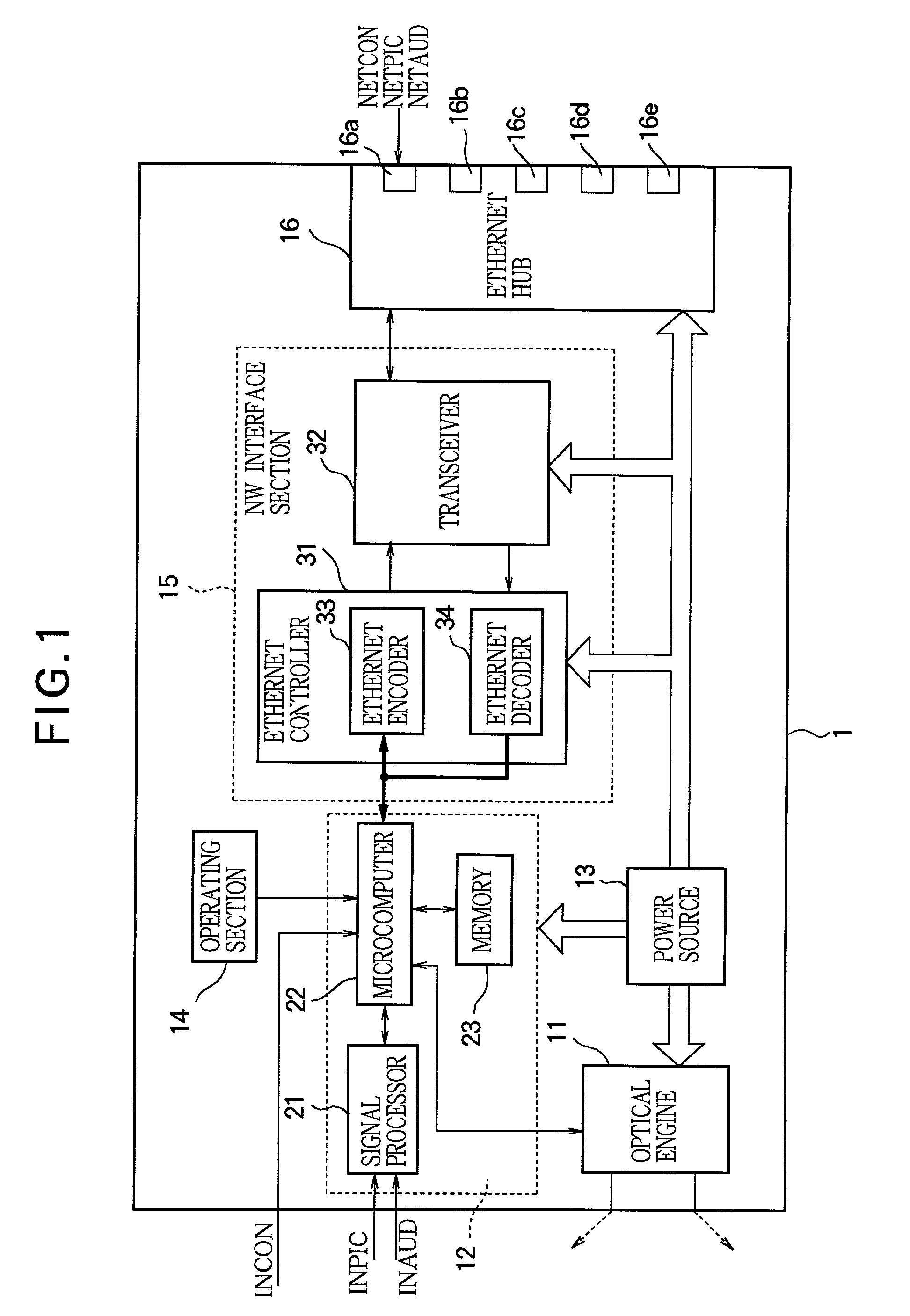
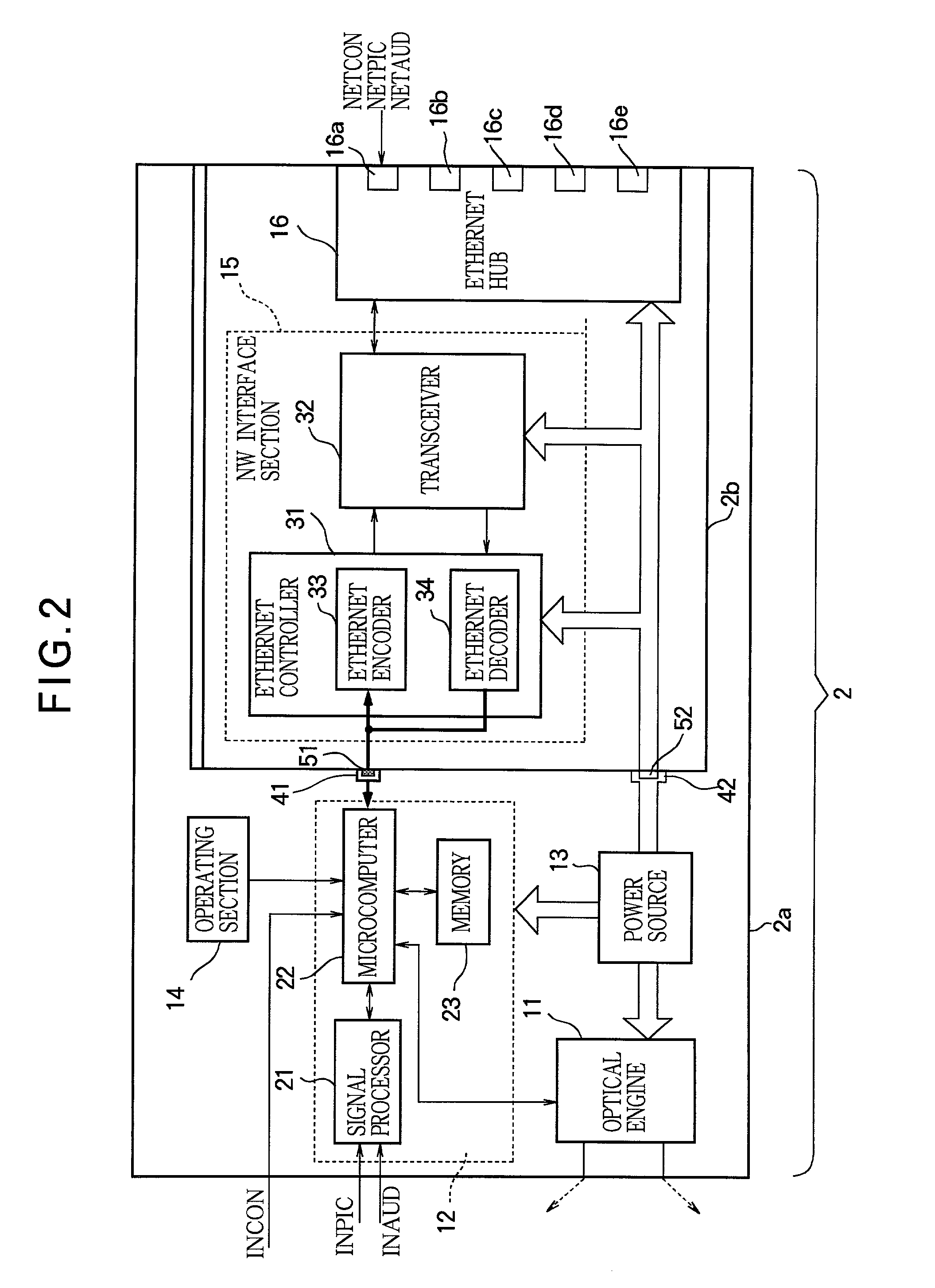
[0046]FIG. 2 is a block diagram schematically showing a projector 2 according to the second embodiment of the present invention, and FIG. 3 is a block diagram schematically showing the projector 2 of FIG. 2 when an interface unit 2b is disconnected. Those structures in FIGS. 2 and 3 that are identical to or correspond to structures in FIG. 1 are assigned identical symbols.

[0047]As shown in FIGS. 2 and 3, the projector 2 comprises a main body 2a and an interface unit 2b that is detachably fitted into the main body 2a. The interface unit 2b is constructed so that it can be connected or disconnected by inserting or withdrawing the interface unit 2b along the guide grooves or members (not shown in the figures) of the main body 2a. Further, the construction for allowing disconnecting or connecting the interface unit 2b is not limited to the guide grooves or members. For instance, connectors 41, 42, 51, and 52 (below described) provided for electrical connection can have ...

Example

Third Embodiment

[0053]FIG. 5 is a block diagram schematically showing a projector 3 according to the third embodiment of the present invention. Those structures in FIG. 5 that are identical to or correspond to structures in FIG. 1 are assigned identical symbols.

[0054]As shown in FIG. 5, the projector 3 according to the third embodiment comprises a main body 3a, and an interface unit 3b that is detachably fitted into the main body 3a. The interface unit 3b is constructed so that it can be connected or disconnected by inserting or withdrawing the interface unit 3b along the guide grooves or members (not shown in the figures) of the main body 2a. Further, the construction for allowing disconnecting or connecting the interface unit 3b is not limited to the guide grooves or members.

[0055]As shown in FIG. 5, the main body 3a of the projector 3 comprises the optical engine 11, the circuit section 12, the power source 13, and the operating section 14. The main body 3a of the projector 3 fur...


PUM


Abstract

A projector comprises an optical engine which projects an image based on a video signal; a circuit section which controls operation of the optical engine; a power source which supplies electric power to the circuit section; a network interface, through which the circuit section communicates with a remote network terminal device; and a hub which is connected to the network interface and includes a plurality of ports. The network interface communicates with the remote network terminal device through one of the ports of the hub. Further, the power source of the projector supplies electric power to the hub.

Description

BACKGROUND OF THE INVENTION[0001]The present invention relates to a projector, such as a liquid crystal projector and a digital micromirror device (DMD) projector, that projects an image based on a video signal on a screen, a network system including a projector, and a method of controlling a projector on a network system.[0002]A projector is capable of displaying a large image, so it is frequently used for a presentation in a conference, a meeting for reading research papers, a new product announcement, and the like. Further, a projector is often used to display an image based on a signal sent from a personal computer (PC) recently. For instance, Japanese Patent Kokai (laid-open) Publication No. 05-289046 discloses a system including one projector and two PCs that are connected to each other through a cable, wherein the projector is capable of displaying an image based on a signal sent from the PCs.[0003]However, there are many users of projectors who are not acquainted with a netw...

Claims


Application Information

Patent Timeline
IPC IPC(8): G03B21/26G03B21/14G03B21/22H04N7/14G03B21/00G06F3/14G09G3/00G09G3/20G09G5/00H04N5/74H04N7/15
CPCG06F3/14G09G3/002G09G5/006H04N5/74H04N21/4788H04N9/3179H04N21/4122H04N21/4143H04N7/17318
Inventor MATOBA, KAZUAKINOSE, JUNICHITADA, JUNJITAMANO, KOUHEIASAKAWA, KATSUMI
Owner MITSUBISHI ELECTRIC CORP
Why Eureka
Try Eureka