Heat treatment system and a method for cooling a loading chamber

a loading chamber and heat treatment technology, applied in the field of vertical heat treatment systems, can solve the problems of high cost, difficult to stably operate the system for a long time, and high cost, and achieve the effect of excellent cooling

Inactive Publication Date: 2006-06-13
TOKYO ELECTRON LTD
View PDF27 Cites 19 Cited by
  • Summary
  • Abstract
  • Description
  • Claims
  • Application Information

AI Technical Summary

Benefits of technology

[0044]The first invention has been made to effectively solve the above described problems. It is an object of the first invention to provide a vertical heat treatment system capable of simplifying the structure of various mechanisms in the vicinity of an opening which is formed in a partition wall separating a housing-box transfer area from a treating-object transfer area (a wafer transfer area), and of contributing to space saving, when an object to be treated is carried in the vertical heat treatment system through the opening to carry out a predetermined treatment.

Problems solved by technology

Therefore, there is a problem in that it is required to ensure a large space for three housing boxes in this portion.
However, in this case, there is a problem in that it is required to provide two opening / closing mechanisms 34A and 34B which have a complicated structure and which are relatively expensive, so that the costs are high.
In particular, in the case of the opening / closing mechanisms 34A and 34B shown in FIG. 9, the structure must be complicatedly devised in order to avoid the interference of the opening / closing mechanisms with each other, so that higher costs are caused.
Therefore, when the wafer boat is carried out of the heat treatment furnace, the wafer transfer mechanism is easy to have the influence of heat from the bottom end opening of the heat treatment furnace and the wafer boat after the heat treatment, and the temperature of the wafer transfer mechanism at the sheltered position sometimes reaches to 150° C., so that it is difficult to stably operate the system for a long term due to the failure of the control apparatus in the wafer transfer mechanism and so forth.
Therefore, the production costs and maintenance costs of the vertical heat treatment system increase, so that it is required to miniaturize the vertical heat treatment system.
There are some cases where the position shift occurs when the holder (boat) is mounted on the holder mounting portion (holder supporting mechanism, boat stage), and there is some possibility that the position error causes errors in the position relationship between the objects and the holder when the objects are transferred.
However, the above described conventional cooling mechanism has the following problems.
When wafers of this large size are carried out of a large-diameter heat treatment furnace which heat-treated the wafers, a large amount of heat is emitted from a throat, and the temperature of the loading area suddenly rises due to a large amount of radiation simultaneously emitted from the large-diameter wafers and the wafer boat, so that there is a problem in that various control parts including electrical parts provided in the area are damaged.
Moreover, this phenomenon that the temperature in the loading area suddenly rises to the high temperature causes a more serious problem in the case of the closed type (inert gas purging box type) system for circulating an inert gas in the area.

Method used


Image

  • Heat treatment system and a method for cooling a loading chamber
  • Heat treatment system and a method for cooling a loading chamber
  • Heat treatment system and a method for cooling a loading chamber

Examples


first preferred embodiment

(Schematic Construction Of Whole Heat Treatment System)

[0204]Referring to the accompanying drawings, the preferred embodiment of the third invention will be described below in detail.

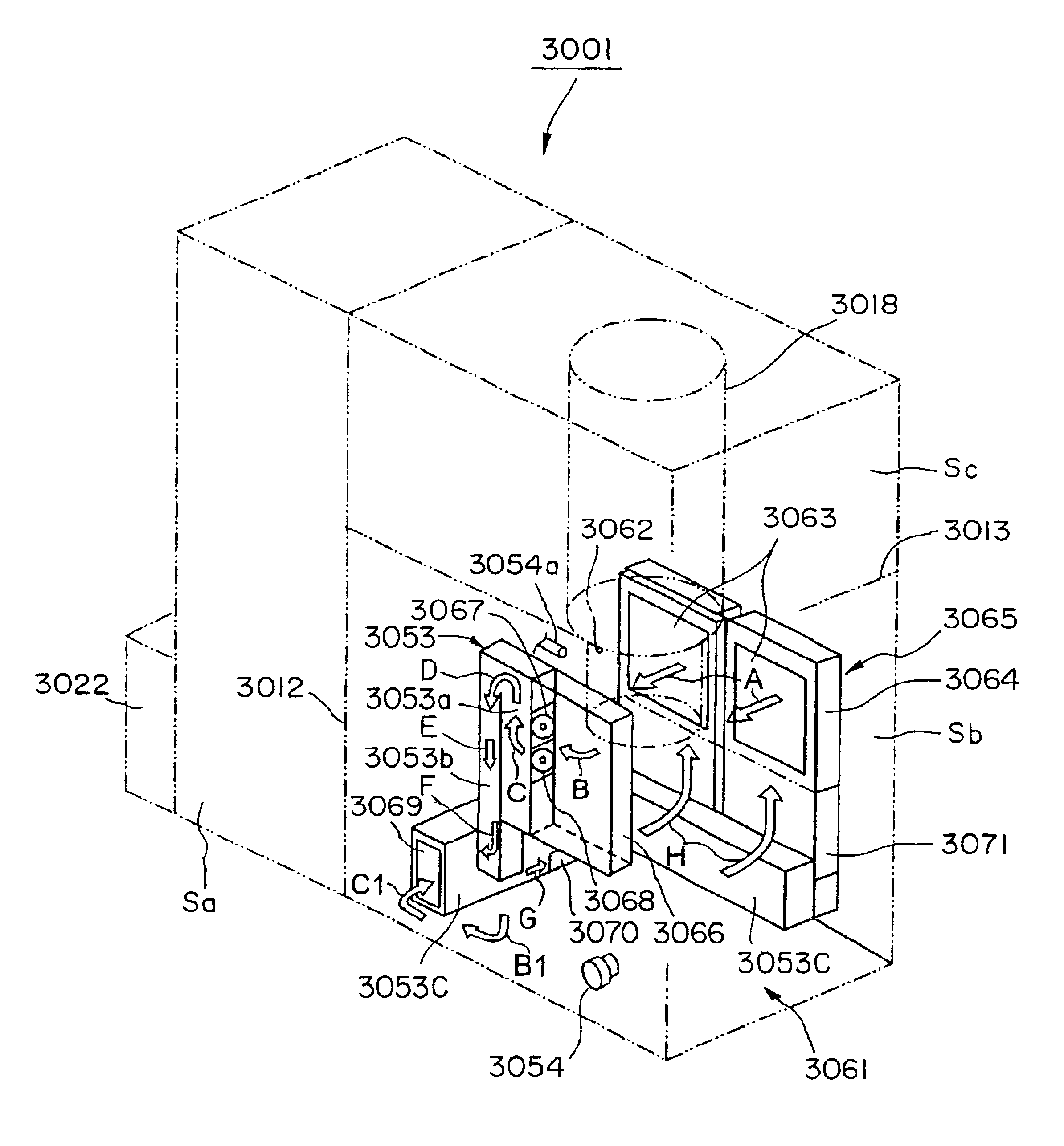
[0205]FIG. 15 is a schematic perspective view of a vertical heat treatment system according to the third invention.

[0206]As shown in FIG. 15, a housing 2010 defining the contour of a vertical heat treatment system is separated by a partition wall 2012 into a carrier transfer area Sa and a loading area Sb.

[0207]In the carrier transfer area Sa, the carrying-in / out, storage and so forth of a carrier, in which semiconductor wafers W (which will be hereinafter referred to as wafers W) serving as objects to be treated (which will be also hereinafter referred as substrates to be treated) have been housed, are carried out. In the loading area Sb, the transfer of the wafers W from the interior of the carrier 2014 to a holder (which will be also hereinafter referred to as a boat) 2016, and the carrying of the hol...


PUM


Abstract

A heat treatment system and method for cooling a loading chamber that includes a heat treatment furnace for heat-treating an object to be treated. The heat treatment furnace includes a throat for carrying the object in and out, and a cooling mechanism for cooling the vicinity of the throat. The cooling mechanism has a ventilating unit with a ventilating port for sending a cooling fluid toward the vicinity of the throat and a heat exchanger arranged so as to face the ventilating port in the vicinity of the throat. The cooling mechanism also has an intake fan for sucking the cooling fluid in the vicinity of the throat over the heat exchanger. When the object to be treated is carried in, the structure of various mechanisms in the vicinity of the throat is simplified, and space is saved.

Description

TECHNICAL FIELD[0001]The first invention relates generally to a vertical heat treatment system utilizing a treating-object housing box for airtightly housing therein objects to be treated, such as semiconductor wafers.[0002]The second invention relates to a vertical heat treatment system used for carrying out a treatment, such as oxidation, diffusion, annealing or CVD, for objects to be treated, such as semiconductor wafers, and a method for controlling the same.[0003]The third invention relates to a vertical heat treatment system for heat-treating objects to be treated, and a method for transferring objects to be treated, and more specifically, relates to a vertical heat treatment system and treating-object transferring method which are capable of aligning a holder for holding objects to be treated.[0004]The fourth invention relates to a heat treatment system for use in steps of fabricating a semiconductor device or the like.BACKGROUND ART[0005]The background of the first invention...

Claims


Application Information

Patent Timeline
Patent Type & Authority Patents(United States)
IPC IPC(8): F27D9/00H01L21/00H01L21/324H01L21/673H01L21/677
CPCF27B5/04F27D3/0084F27D5/0037H01L21/67017H01L21/67109H01L21/67373H01L21/67379H01L21/67389H01L21/67393H01L21/67769H01L21/67772H01L21/67775H01L21/67778H01L21/68707F27B17/0025Y10S414/135H01L21/67739Y10S269/903Y10S414/137H01L21/324
Inventor SAKATA, KAZUNARIHASEGAWA, KOYUKATABUCHI, KEIICHIWATANABE, SHINGOMOCHIZUKI, SHINYAAKIMOTO, MOTOKIMOTONO, HIROSHI
Owner TOKYO ELECTRON LTD
Why Eureka
Try Eureka