
Substantially constant-force exercise machine

a technology of resistance modules and exercise machines, applied in the field of exercise machines, can solve the problems of posing the risk of injury to users, providing an exercise system that is difficult to move and compactly store, and the machine is very heavy and difficult to move, and achieves the effect of constant resistance for

Active Publication Date: 2006-06-13
BRIGHAM YOUNG UNIV
View PDF22 Cites 17 Cited by
  • Summary
  • Abstract
  • Description
  • Claims
  • Application Information

AI Technical Summary

Benefits of technology

[0009]It has been recognized that it would be advantageous to develop a resistance module for use in exercise machines that provides a substantially constant resistance force through a range of motion. In addition,...

Problems solved by technology

While free weights are effective in providing a substantially constant force through a range of motion, free weights are necessarily heavy and often bulky, posing the risk of injury to a user and providing an exercise system that can be difficult to move and compactly store.
Exercise machines utilizing weight systems suffer from many of the problems associated with free weights in that the machines can be very heavy and difficult to move.
Also, springs have been incorporated into exercise machines for use in low-gravity environments, where the gravitational force is sufficiently low as to negate the effectiveness of weight training.
While springs have been used with some success to simulate the resistance provided by free weights or weight systems, springs have also proved problematic as resistance members.
As the goal of most resistance exercises is to provide constant resistance through a range of motion, conventional springs have thus proved problematic as weight substitutes in exercise equipment.

Method used


Image

  • Substantially constant-force exercise machine
  • Substantially constant-force exercise machine
  • Substantially constant-force exercise machine

Examples


Embodiment Construction

[0024]Reference will now be made to the exemplary embodiments illustrated in the drawings, and specific language will be used herein to describe the same. It will nevertheless be understood that no limitation of the scope of the invention is thereby intended. Alterations and further modifications of the inventive features illustrated herein, and additional applications of the principles of the inventions as illustrated herein, which would occur to one skilled in the relevant art and having possession of this disclosure, are to be considered within the scope of the invention.

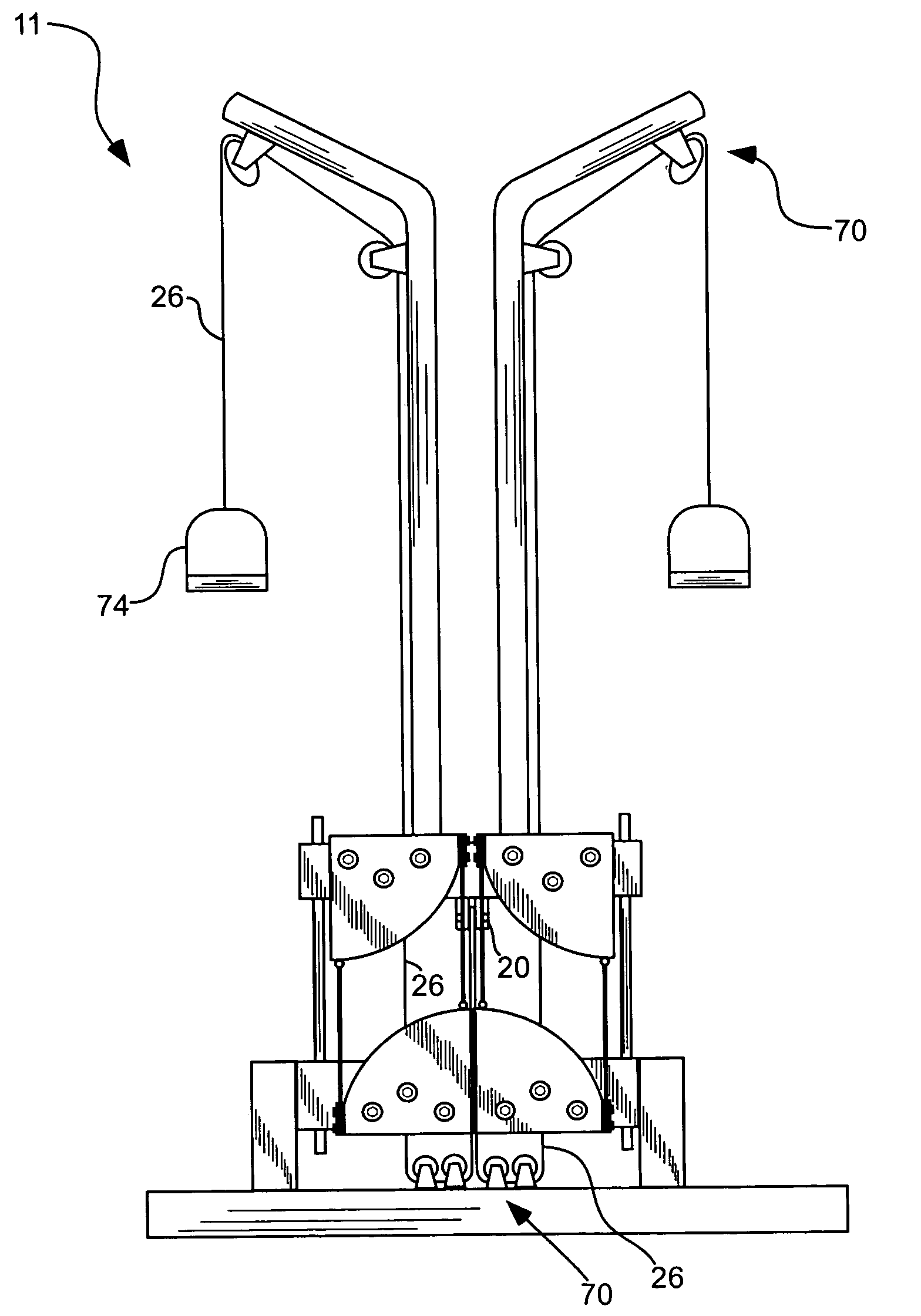
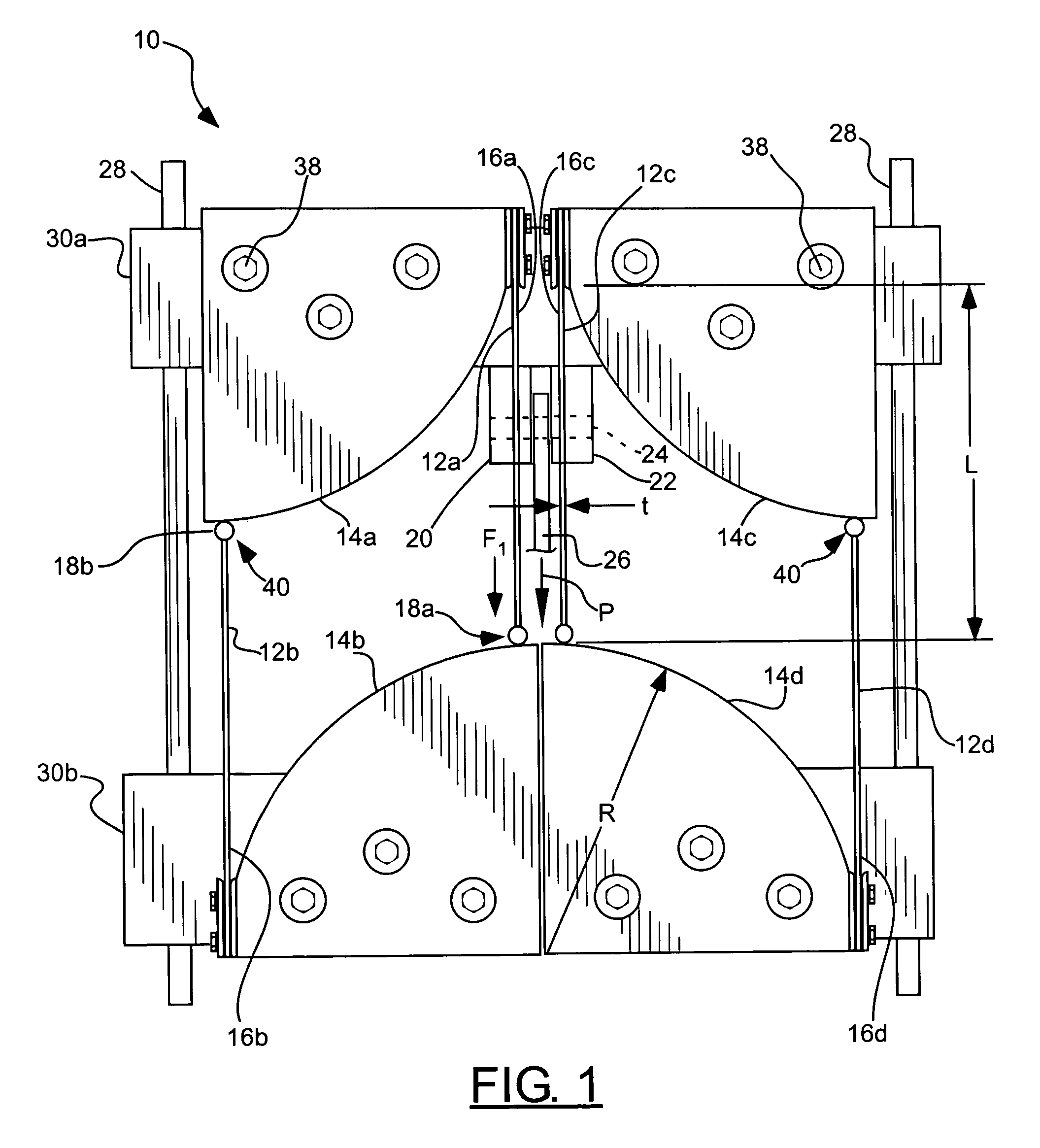
[0025]The present invention provides one or more resistance modules for providing a substantially constant force through a range of motion for an exercise machine. Exercise machines, physical fitness, weight training, and health maintenance are examples of fields that can benefit from use of the present invention. For example, the module can be incorporated into an exercise machine 11, shown by way of example in ...


PUM


Abstract

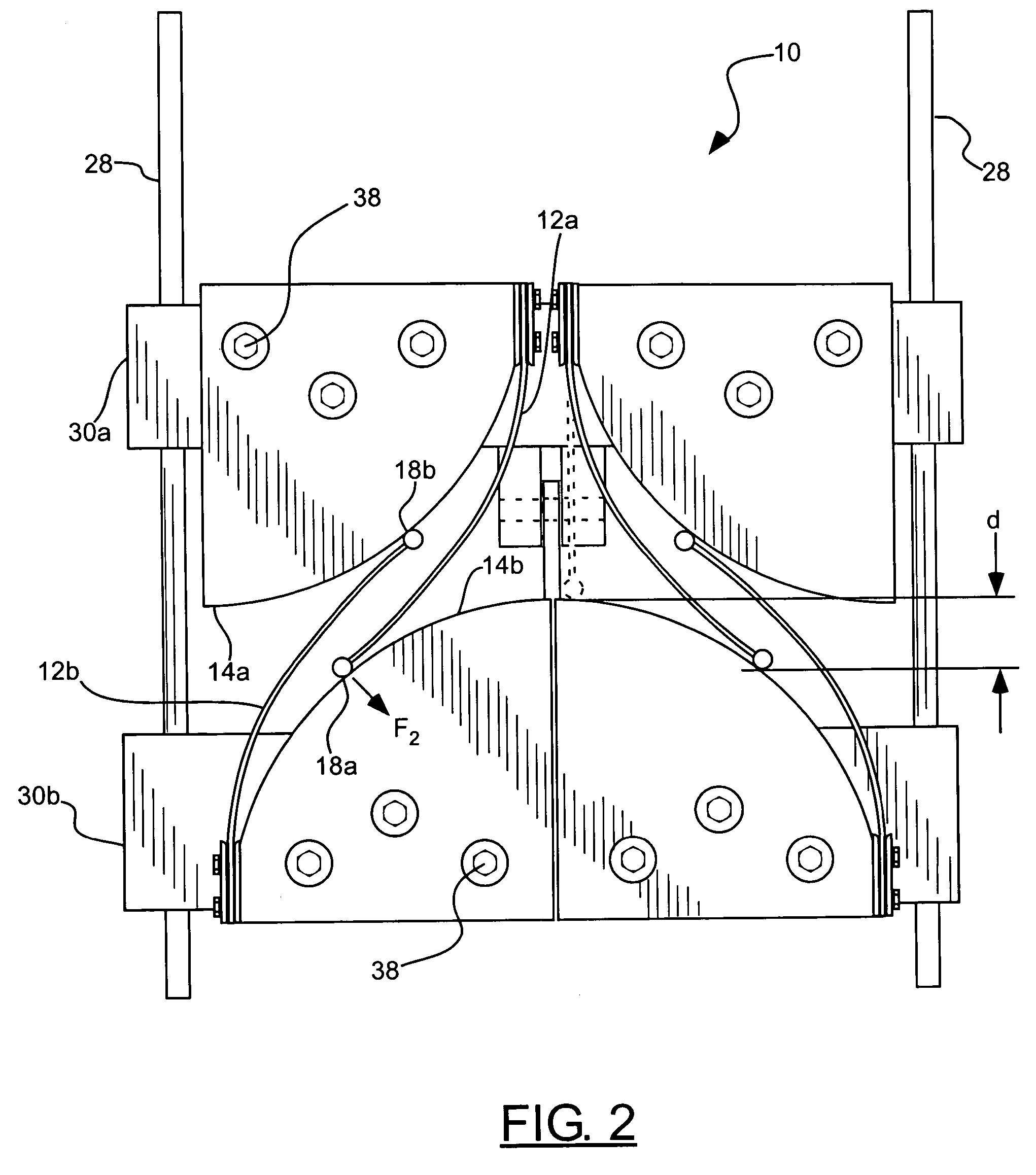
A resistance module for an exercise machine for providing a substantially constant force through a range of motion includes at least one cantilever spring and at least one rigid member movable with respect to one another along a path of travel. The rigid member causes the cantilever spring to deflect and produce a resistance force. The cantilever spring has an anchored end and a deflection end. The rigid member engages the deflection end of the cantilever spring, and constrains the deflection end to a predetermined path of deflection as the cantilever spring and the rigid member move with respect to one another. The rigid member can be a non-planer contact surface along which the deflection end tracks, or a pivot link. The module can include means for operatively coupling at least one of the cantilever spring and the at least one rigid member to an exercise machine.

Description

[0001]Priority is claimed from U.S. Provisional Patent Application No. 60 / 460,471, filed Apr. 2, 2003, which is hereby incorporated herein by reference.BACKGROUND OF THE INVENTION[0002]1. Field of the Invention[0003]The present invention relates generally to exercise machines. More particularly, the present invention relates to substantially constant-force resistance modules for use in exercise machines.[0004]2. Related Art[0005]The value of resistance training has been recognized for many years. The goal of most resistance training exercises is to provide resistance to movement by a user such that the user's musculature is strained while displacing a load. So-called “free weights” are perhaps the simplest manner in which to provide this resistance, as a user can simply lift a weight while gravity acts on the mass of the weight to provide resistance to the user's motions. Because the force of gravity is sufficiently constant through a range of motion a human user can replicate, free...

Claims


Application Information

Patent Timeline
IPC IPC(8): A63B21/02A63B21/00A63B21/002A63B21/04A63B23/12
CPCA63B21/026A63B21/00069A63B23/12A63B21/002A63B23/1209A63B23/03533A63B23/03541A63B21/4043A63B21/4035
Inventor HOWELL, LARRY L.MAGLEBY, SPENCER P.
Owner BRIGHAM YOUNG UNIV
Learn More