Orthosis providing dynamic tracking of the patello-femoral joint

a dynamic tracking and orthosis technology, applied in the field of knee orthoses, can solve the problems of subluxation or dislocation of the patella due to patellar tracking errors, the greatest risk of subluxation or dislocation, and the high risk of patellar functional disorders, so as to increase the tension force, reduce the tension force, and increase the tension force

Inactive Publication Date: 2006-06-13
BREG
View PDF35 Cites 64 Cited by
  • Summary
  • Abstract
  • Description
  • Claims
  • Application Information

AI Technical Summary

Benefits of technology

[0009]When the first upper and lower arms and tension strap lever rotationally transition from the flexion position to the extension position, the tension strap connection point is posteriorly displaced relative to the hinge pivot more distal from the patella, thereby increasing the tension force applied to the compression member. Conversely, when the first upper and lower arms and tension strap lever rotationally transition from the extension position to the flexion position, the tension strap connection point is anteriorly displaced relative to the hinge pivot more proximal to the patella, thereby decreasing the tension force applied to the compression member. The orthosis is further provided with a counterbalance connector connected to the compression member and oriented counter to the tension strap.
[0010]The present orthosis enables a method for maintaining proper tracking of the patella relative to the femoral head during range of motion movement of the knee. The method is initiated by placing the compressio

Problems solved by technology

In still more severe forms of patello-femoral joint disorder, patellar tracking errors result in subluxation or dislocation of the joint.
Minor subluxation is often the result of a functional imbalance in the knee.
In addition, subluxation or dislocation of the patella

Method used


Image

  • Orthosis providing dynamic tracking of the patello-femoral joint
  • Orthosis providing dynamic tracking of the patello-femoral joint
  • Orthosis providing dynamic tracking of the patello-femoral joint

Examples


Embodiment Construction

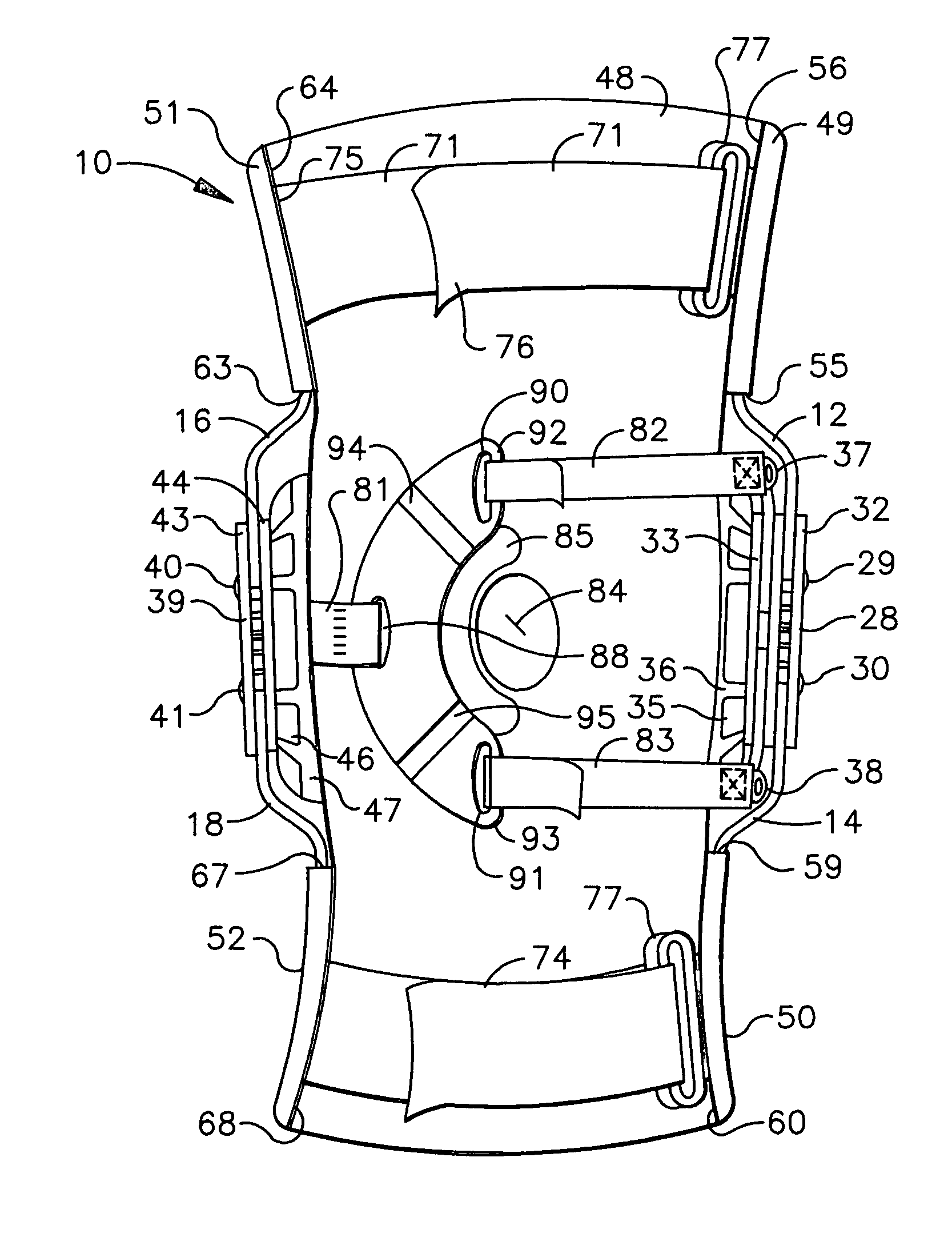
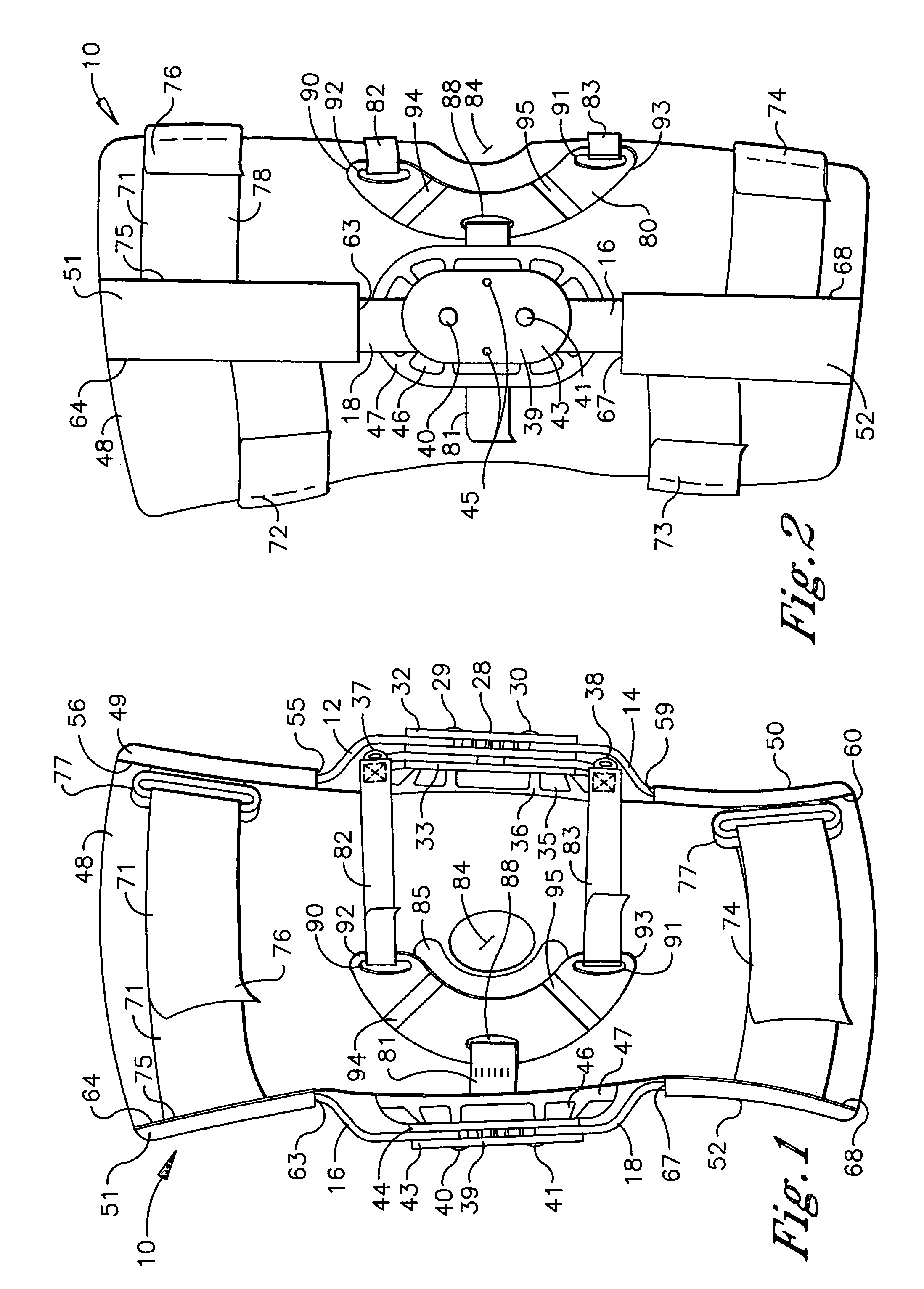
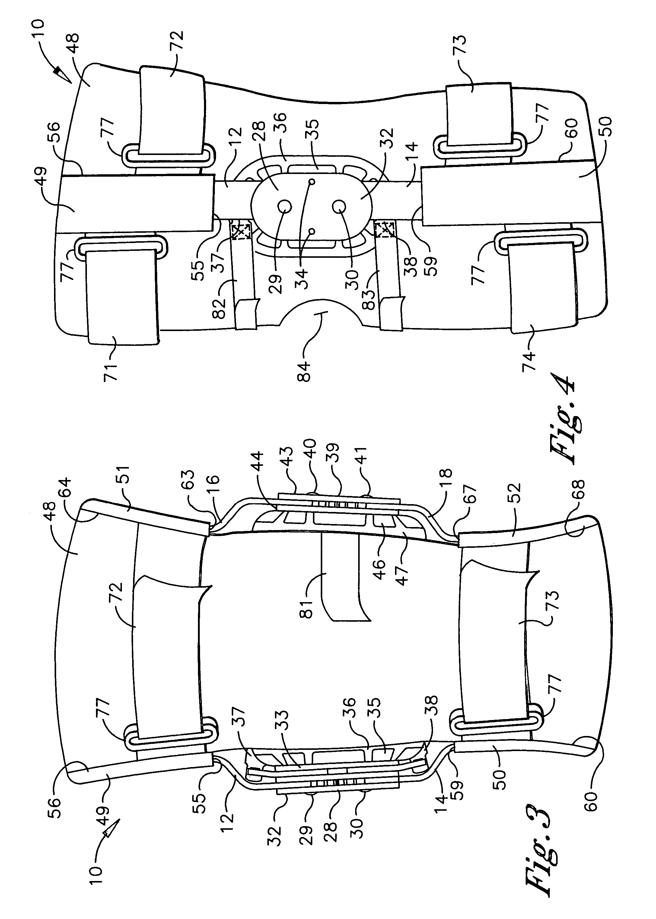
[0022]Referring to FIGS. 1–5, the knee orthosis of the present invention is shown and generally designated 10. The positional terms, upper, lower, lateral, medial, anterior and posterior, are used herein with reference to the normal orientation of a knee on which the knee orthosis 10 is mounted in practice as described hereafter.

[0023]The knee orthosis 10 has a first pair of arms positioned on one side of the orthosis 10 and a second pair of arms positioned on the opposite side of the orthosis 10. The first pair of arms consists of a first upper arm 12 and a first lower arm 14. The second pair consists of a second upper arm 16 and a second lower arm 18. The first upper arm 12 defines an upper end 20 and a lower end 21, the first lower arm 14 defines an upper end 22 and a lower end 23, the second upper arm 16 defines an upper end 24 and a lower end 25, and the second lower arm 18 defines an upper end 26 and a lower end 27. The arms 12, 14, 16, 18 each have a bar-shaped configuration ...


PUM


Abstract

A knee orthosis is provided having upper and lower arms and a hinge assembly positionable about the knee to one side of the patella. The hinge assembly has a hinge pivot and a tension strap lever. The upper and lower arms and tension strap lever are each rotatable about the hinge pivot. A compression member is positioned in engagement with the knee on the opposite side of the patella from the hinge assembly and a tension strap is connected to the compression member and the tension strap lever. The tension strap applies a tension force to the compression member which increases when the upper and lower arms and tension strap lever rotationally transition from a flexion position to an extension position and decreases when the upper and lower arms and tension strap lever rotationally transition from the extension position to the flexion position.

Description

[0001]This a continuation-in-part application of Ser. No. 09 / 669,061 filed on Sep. 22, 2000 now U.S. Pat. No. 6,551,264.TECHNICAL FIELD[0002]The present invention relates generally to knee orthoses, and more particularly to a knee orthosis which causes the patella to properly track the trochlear groove during movement of the knee.BACKGROUND OF THE INVENTION[0003]The patello-femoral joint of the knee is an articulation between the patella and femur. The joint consists of an articular surface on the posterior of the patella and a corresponding articular surface on the anterior of the head of the femur which is termed the trochlea. The posterior of the patella is contoured as a ridge, while the trochlea is contoured as a groove which is dimensioned to receive the patellar ridge in a complementary manner. Proper dynamic function of the patello-femoral joint requires that the patellar ridge accurately track the underlying trochlear groove when the knee is moved through flexion or extensi...

Claims


Application Information

Patent Timeline
IPC IPC(8): A61F5/00A61F5/01
CPCA61F5/0125A61F2005/0176
Inventor MASON, JEFFREY T.FOUT, JAMES M.
Owner BREG
Why Eureka
Try Eureka