Dialysis procedure catheter

a catheter and dialysis technology, applied in the field of new dialysis procedure catheters, can solve the problem of not disclosing a new dialysis procedure catheter, and achieve the effect of convenient and accurate needle insertion into the body of the dialysis patient, convenient and convenient us

Inactive Publication Date: 2006-06-13
SIMPSON VICKI J +1
View PDF12 Cites 37 Cited by
  • Summary
  • Abstract
  • Description
  • Claims
  • Application Information

AI Technical Summary

Benefits of technology

[0011]Still another object of the present invention is to provide a new dialysis procedure catheter for accurately and facilitating insertion of a needle into a dialysis patient's body.
[0012]Still yet another object of the present invention is to provide

Problems solved by technology

While these devices fulfill their respective, particular objectives and requireme

Method used


Image

  • Dialysis procedure catheter
  • Dialysis procedure catheter
  • Dialysis procedure catheter

Examples


Embodiment Construction

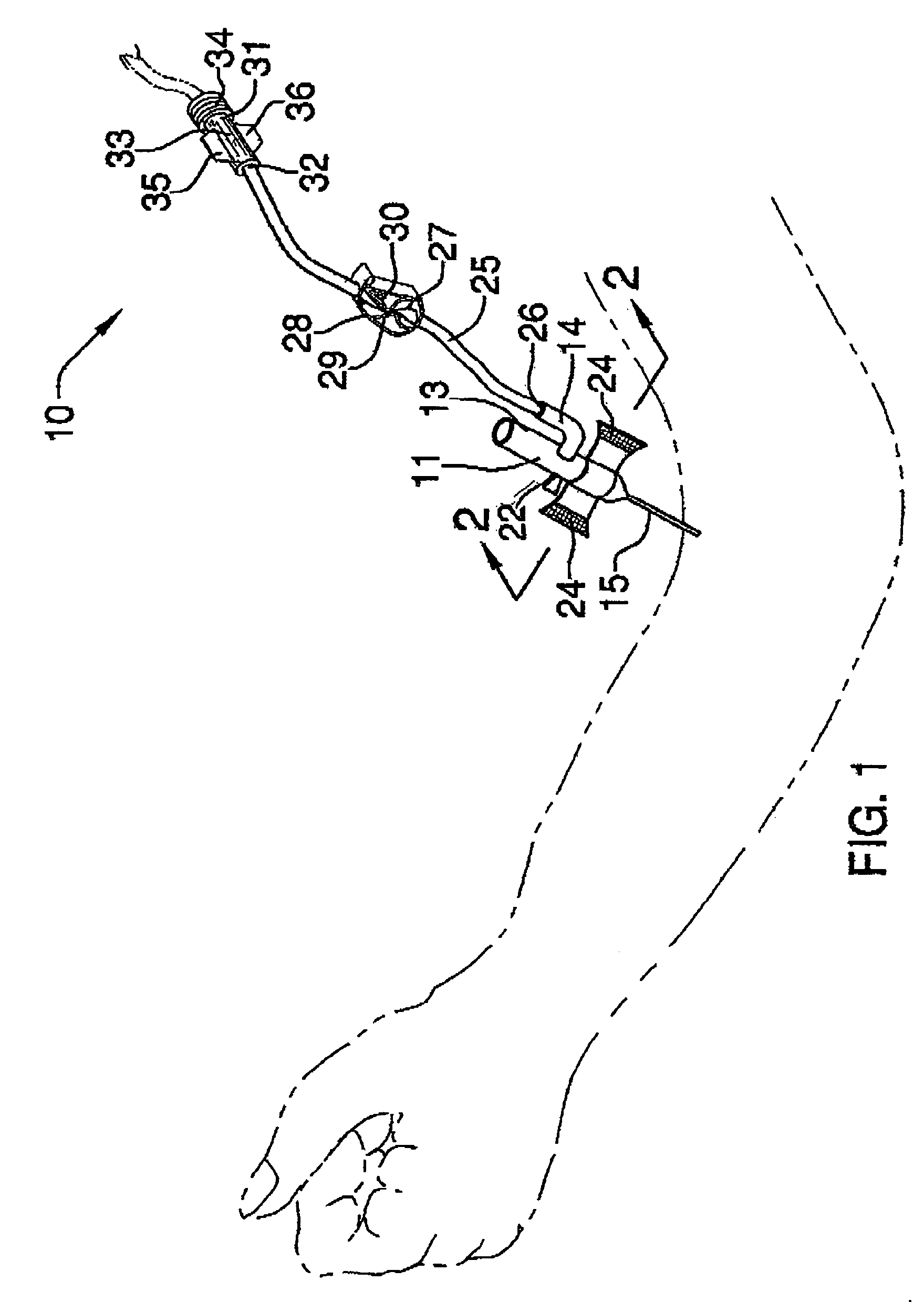
[0019]With reference now to the drawings, and in particular to FIGS. 1 through 3 thereof, a new dialysis procedure catheter embodying the principles and concepts of the present invention and generally designated by the reference numeral 10 will be described.

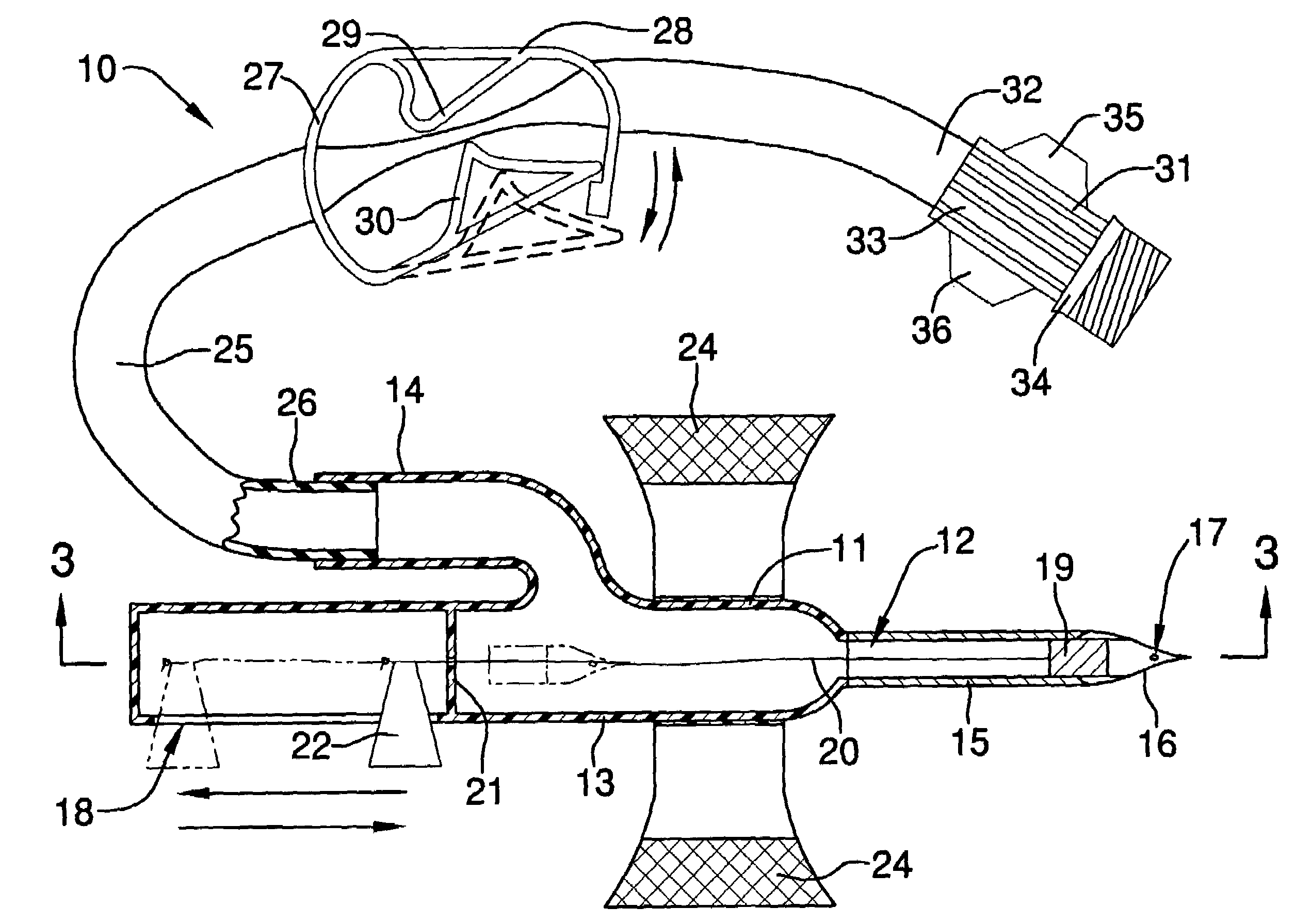
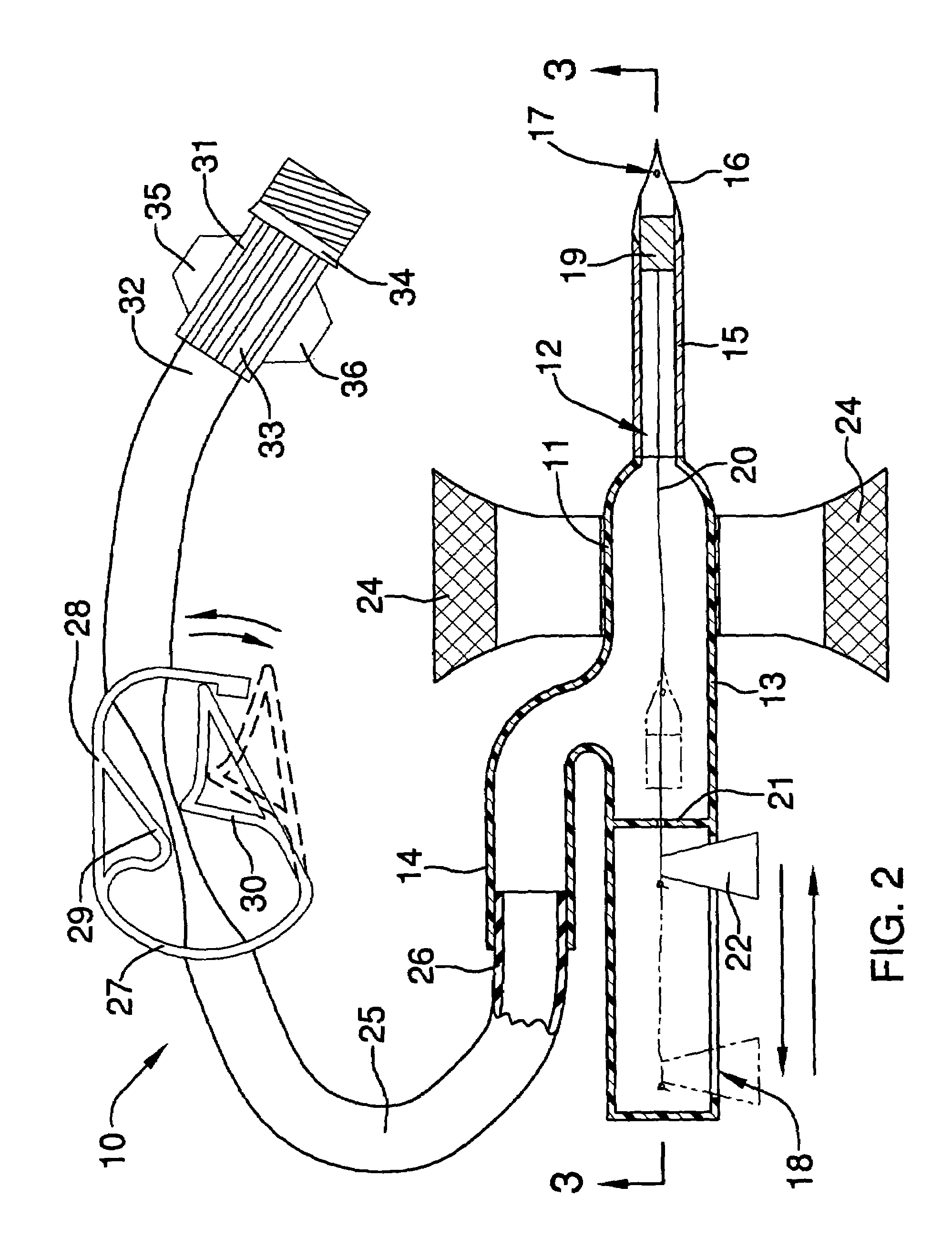
[0020]As best illustrated in FIGS. 1 through 3, the dialysis procedure catheter 10 generally comprises a tubular member 11 having a bore 12 being disposed therethrough, and also having an enlarged main portion 13 and a branch portion 14, and further having a needle 15. The needle 15 is conventionally connected to the enlarged main portion 13, and has a tapered end 16 for penetrating through a user's skin and vessels, and further has a non-vacuum aperture 17 being disposed through a wall of the needle 15 near the tapered end 16. The enlarged main portion 13 of the tubular member 11 has a longitudinal slot 18 being disposed through a side wall thereof.

[0021]A plug assembly includes a plug member 19 being removably disposed in the b...


PUM


Abstract

A dialysis procedure catheter for accurately facilitating insertion of a needle into a dialysis patient's body. The dialysis procedure catheter includes a tubular member having a bore being disposed therethrough, and also having an enlarged main portion and a branch portion, and further having a needle; and also includes a plug assembly including a plug member being removably disposed in the bore of the needle; and further includes a handle being attached to the enlarged main portion of the tubular member; and also includes a hose having a first end being attached to the branch portion; and further includes a hose clamp for crimping the hose; and also includes a hose connector being attached to a second end of the hose for connecting to a dialysis machine.

Description

BACKGROUND OF THE INVENTION[0001]1. Field of the Invention[0002]The present invention relates to dialysis catheters and more particularly pertains to a new dialysis procedure catheter for accurately facilitating insertion of a needle into a dialysis patient's body.[0003]2. Description of the Prior Art[0004]The use of dialysis catheters is known in the prior art. More specifically, dialysis catheters heretofore devised and utilized are known to consist basically of familiar, expected and obvious structural configurations, notwithstanding the myriad of designs encompassed by the crowded prior art which have been developed for the fulfillment of countless objectives and requirements.[0005]Known prior art includes U.S. Pat. No. 5,941,854; U.S. Pat. No. 6,042,566; U.S. Pat. No. 5,843,038; U.S. Pat. No. 6,027,492; U.S. Pat. No. 5,092,853; and U.S. Patent No. Des. 403,064.[0006]While these devices fulfill their respective, particular objectives and requirements, the aforementioned patents ...

Claims


Application Information

Patent Timeline
IPC IPC(8): A61M25/16
CPCA61M1/3661A61M25/065A61M25/0612A61M25/0637A61M39/20
Inventor SIMPSON, VICKI J.SIMPSON, JAMES D.
Owner SIMPSON VICKI J
Why Eureka
Try Eureka