Check patentability & draft patents in minutes with Patsnap Eureka AI!

Deflection yoke having magnets for correcting raster distortion and cathode-ray tube apparatus having the deflection yoke

a technology of deflection yoke and cathode tube, which is applied in the direction of cathode ray tube/electron beam tube, electric discharge tube, electrical apparatus, etc., can solve the problem of overall decrease in the magnetic field lines running out of the magnet, and achieve good adjustment of magnetization and high quality performance

Inactive Publication Date: 2006-06-13
PANASONIC CORP
View PDF12 Cites 3 Cited by
  • Summary
  • Abstract
  • Description
  • Claims
  • Application Information

AI Technical Summary

Benefits of technology

The solution ensures stable correction of raster distortion across temperature changes and reduces the variation in magnetization, improving the performance of CRT apparatus with flat panels by efficiently adjusting magnetic field lines and maintaining high-quality image display.

Problems solved by technology

In the deflection yoke, the magnetization of the magnet decreases in response to an increase in temperature, which results in an overall decrease in the magnetic field lines running out of the magnet.

Method used


Image

  • Deflection yoke having magnets for correcting raster distortion and cathode-ray tube apparatus having the deflection yoke
  • Deflection yoke having magnets for correcting raster distortion and cathode-ray tube apparatus having the deflection yoke
  • Deflection yoke having magnets for correcting raster distortion and cathode-ray tube apparatus having the deflection yoke

Examples


Embodiment Construction

[0047]A CRT apparatus 1 is given below by way of example to illustrate the best embodiment of the present invention.

(1) Overall Structure of the CRT Apparatus 1

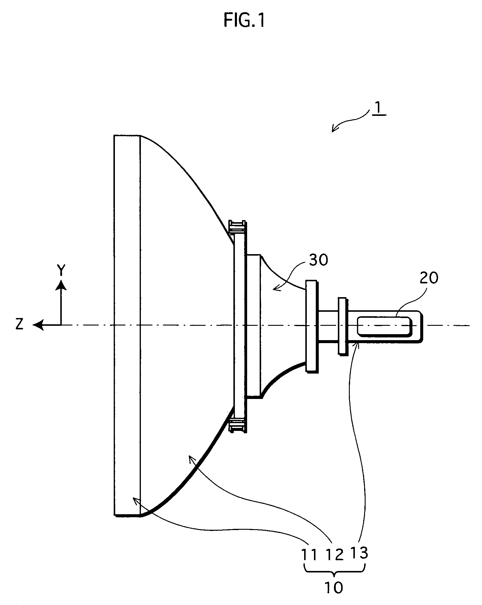
[0048]The overall structure of the CRT apparatus 1 is described by the aid of FIG. 1. FIG. 1 is a side view of the CRT apparatus 1 with selected main components thereof.

[0049]As shown in FIG. 1, the CRT apparatus 1 has an air-tightened container, the CRT 10, and a deflection yoke 30 set on the periphery of the CRT 10. The CRT 10 is composed of a panel 11 with a phosphor screen (not shown) provided inside; a neck 13 where an electron gun 20 is mounted; and a funnel 12 jointing the panel 11 and the neck 13.

[0050]The electron gun 20 is an inline gun and comprises firing units for three electron beams of blue (B), green (G), and red (R).

[0051]The deflection yoke 30, whose structure is described later, is placed in the space between the funnel 12 and the neck 13 of the CRT 10 so as to follow the periphery of these two.
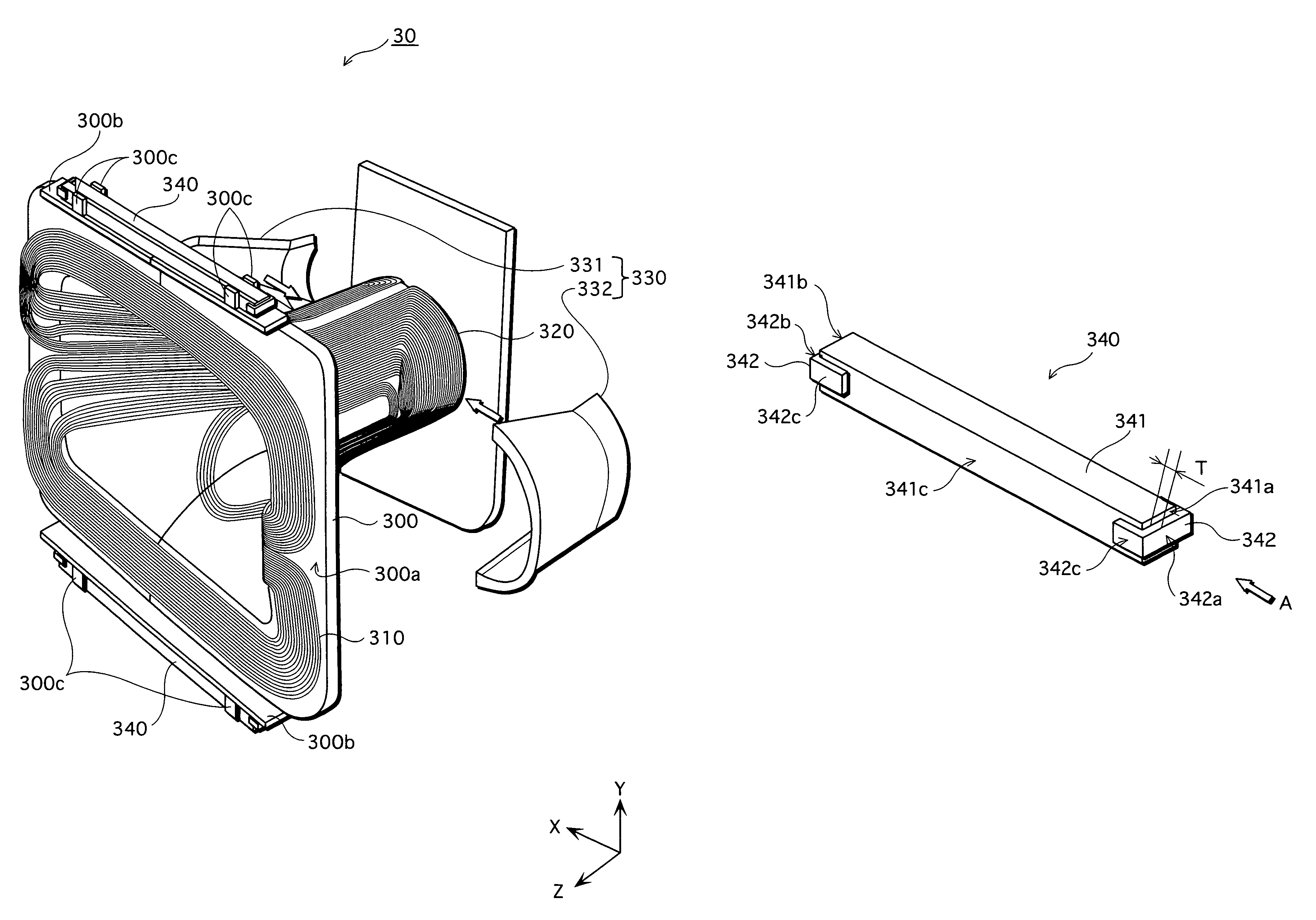
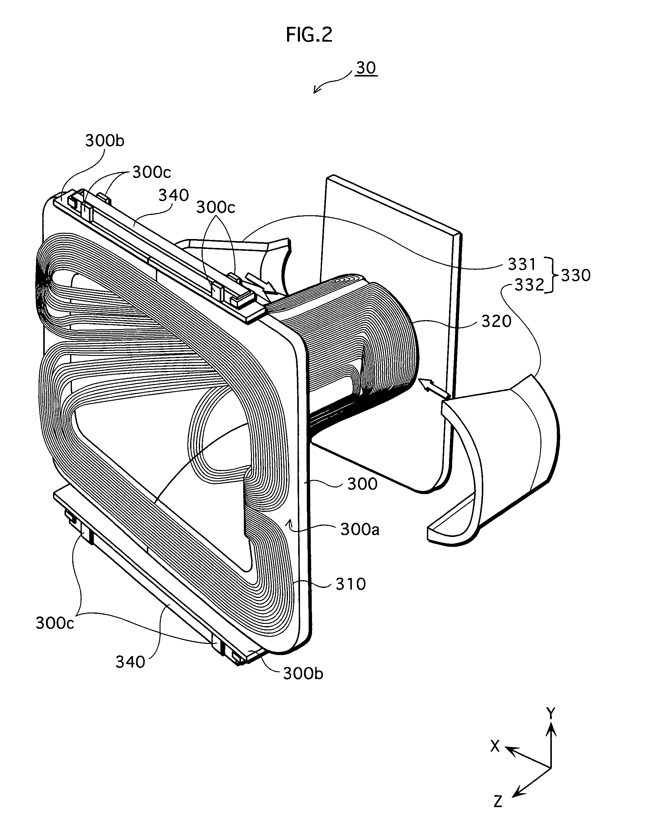
(2) Structur...


PUM


Abstract

A permanent magnet is selectively picked for a deflection yoke and provided on the periphery of the cathode ray tube for controlling the direction of an electron beam emitted towards a screen from an electron gun. The permanent magnet can adjust an irradiating point of the electron beam. The permanent magnet incorporates a magnetic substance that can be applied to at least one of the end faces of the magnet with a negative temperature characteristic. The magnetic substances can have different configurations and based on the saturation flux density of the permanent magnet, can be selected to match the permanent magnet to correct variation in the saturation flux density.

Description

TECHNICAL FIELD[0001]The present invention relates to a deflection yoke and a cathode-ray tube apparatus, and especially relates to a technology of raster distortion correction.BACKGROUND ART[0002]In a cathode-ray tube (hereafter CRT) apparatus used in televisions and the like, electron beams are emitted from the electron gun and deflected by a magnetic field which is created by the deflection yoke provided on the periphery of the funnel of the CRT. These deflected electron beams scan over the panel, which results in visual display. Here, the panel provided with a screen, which is a face irradiated by the electron beams, does not have a spherical surface centering on the deflection center of the electron beams, and the distance between the deflection center and a point irradiated by the electron beams increases towards the perimeter of the screen. Consequentially, deviation of the electron beams becomes most significant in the four corners of the screen, which leads to one type of r...

Claims


Application Information

Patent Timeline
Patent Type & Authority Patents(United States)
IPC IPC(8): H01J29/70H01J29/46H01J29/76
CPCH01J29/701H01J29/76H01J2229/5682
Inventor IWASAKI, KATSUYO
Owner PANASONIC CORP
Features
  • R&D
  • Intellectual Property
  • Life Sciences
  • Materials
  • Tech Scout
  • Unparalleled Data Quality
  • Higher Quality Content
  • 60% Fewer Hallucinations
Learn More