Calibration method for density in image forming apparatus

a technology of density and image forming apparatus, which is applied in the direction of image enhancement, digital output to print units, instruments, etc., can solve the problems of inability to obtain desired output characteristics, inability to maintain the effect of software calibration, and inability to obtain stable absolute density of print results

Inactive Publication Date: 2006-06-13
CANON KK
View PDF11 Cites 68 Cited by
  • Summary
  • Abstract
  • Description
  • Claims
  • Application Information

AI Technical Summary

Benefits of technology

[0018]An object of the present invention is to provide a calibration method which can solve the above-mentioned drawbacks.

Problems solved by technology

The print environments may, for example, include temperature and humidity of an atmosphere into which the apparatus is installed, and, if such print environment is changed, an amount of toner adhered to the print medium may be changed in electrophotographic systems or an ink discharged amount may be changed in ink jet systems, with the result that desired output characteristics may not be obtained.
In a case where a plurality of print apparatuses are used via a network as is in information processing systems, the change in the print characteristics of various print apparatuses causes another problem.
For example, in accordance with the user's instruction, even when the software calibration is effected at a certain timing, since the device calibration is generated at the predetermined timing individually determined in the print apparatus, the output characteristics of the printer engine are changed due to the device calibration, with the result that the effect of the software calibration is not maintained.
In this case, particularly, the print result having the stable absolute density cannot be obtained.
However, in the arrangement in which the software calibration is correlated with the device calibration, if image processing conditions for effecting the respective calibrations (for example, binarizing or multi-value obtaining) are different, the fine adjustment may not be performed with high accuracy.
In such a case, it cannot be said that the calibration data obtained by the software calibration is well matched to the correction data of the calibration data obtained by the device calibration, with the result that the calibration data accurately reflecting the output characteristics of the print apparatuses cannot be obtained.

Method used


Image

  • Calibration method for density in image forming apparatus
  • Calibration method for density in image forming apparatus
  • Calibration method for density in image forming apparatus

Examples


Embodiment Construction

[0037]The present invention will now be fully explained in connection with embodiments thereof with reference to the accompanying drawings.

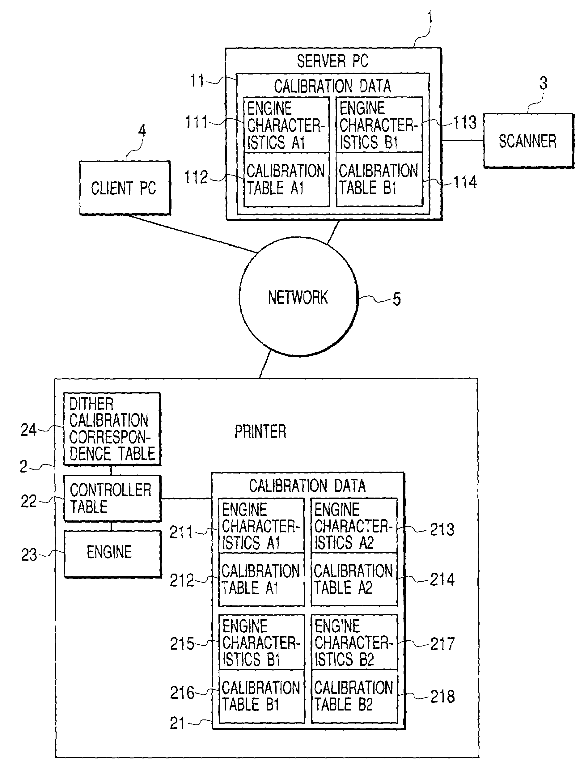
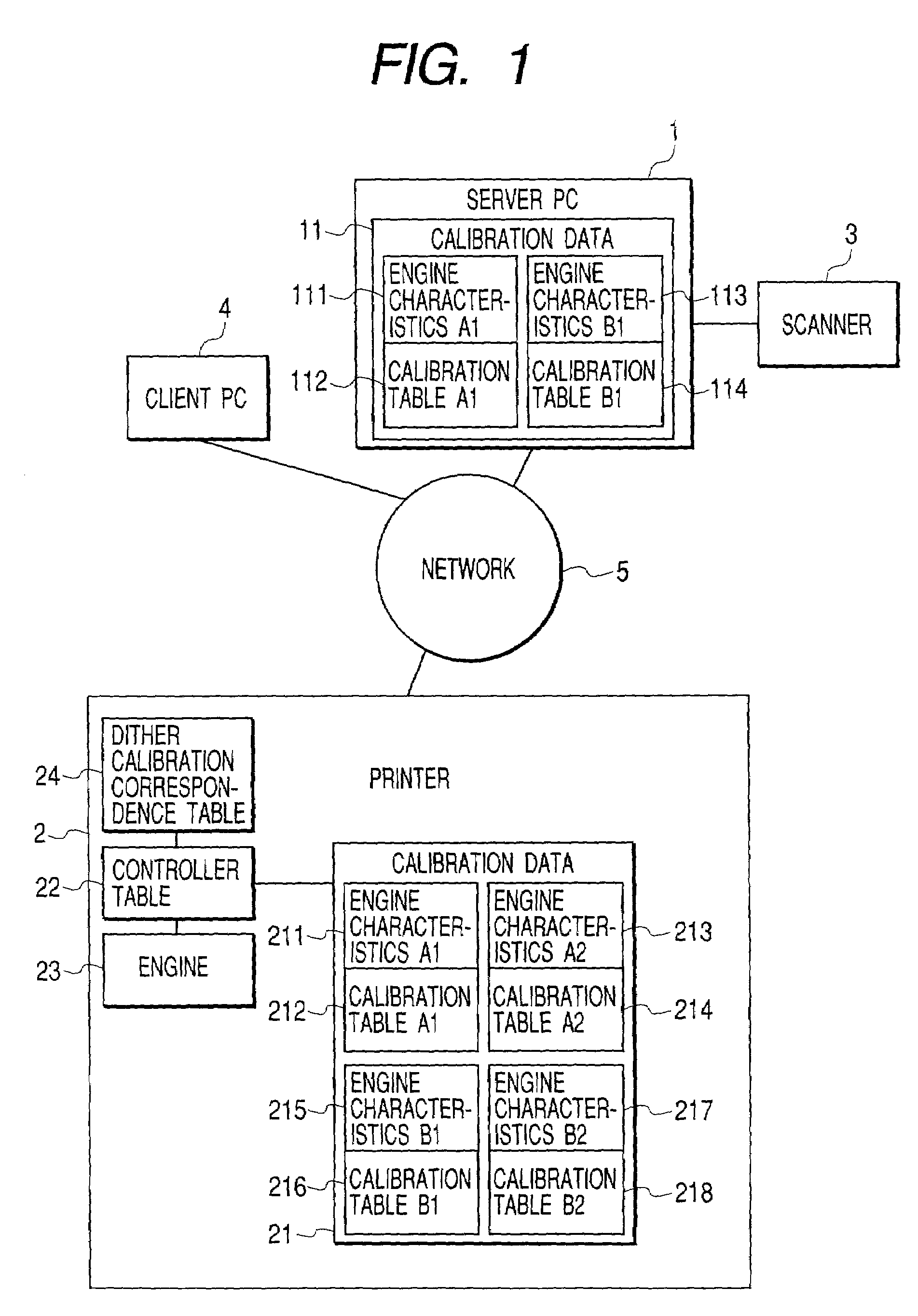
[0038]Incidentally, in an embodiment described hereinbelow, while an example that a color laser beam printer (LBP) is used as a printer apparatus constituting a system will be explained, it should be noted that the present invention can similarly be applied to print apparatuses such as other printers (for example, ink jet printer) and a copying machine. Further, while an example that four kinds of halftone patterns according to a dither method as image processing conditions are used will be explained, it is apparent that the present invention can be applied to many kinds of patterns, from the following explanation.

[0039]In an illustrated embodiment, regarding dither methods as binarizing or n-value (n>2) obtaining methods as the image processing conditions, four kinds of dither methods of dot concentration type are used, and software calibration ...


PUM


Abstract

Calibration associated with output density correction of a printer is effected by software calibration manipulated by the user and device calibration automatically performed by the printer, and, regarding these calibrations, high accurate calibration in which dither patterns for binarizing processing are matched to each other is effected.
In a system in which either one of halftone patterns A, B, C and D as dither patterns can be used, regarding fewer number of patterns A and B, second calibration tables are created by correcting first calibration tables based on the software calibration by using correction data of engine characteristics based on the device calibration. Among the usable halftone patterns, the calibration table corresponding to the pattern A or B is selected in accordance with the set halftone pattern, and the output density correction by using the selected table.

Description

BACKGROUND OF THE INVENTION[0001]1. Field of the Invention[0002]The present invention relates to a calibration method for maintaining a print density characteristics constant in an image forming apparatus.[0003]2. Related Background Art[0004]In color printers, copying machines and print apparatuses for printing characters and / or images on a print medium such as a paper, in general, it is known that print output characteristics such as gradation, density and the like in a print result may be varied with change in print environments and / or time-lapse change of the apparatus itself.[0005]The print environments may, for example, include temperature and humidity of an atmosphere into which the apparatus is installed, and, if such print environment is changed, an amount of toner adhered to the print medium may be changed in electrophotographic systems or an ink discharged amount may be changed in ink jet systems, with the result that desired output characteristics may not be obtained. Fur...

Claims


Application Information

Patent Timeline
Patent Type & Authority Patents(United States)
IPC IPC(8): G06K15/00B41J29/46B41J2/52G06F3/12G06T5/00H04N1/407H04N1/60
CPCH04N1/6033H04N1/4078
Inventor NAKAJIMA, NOBUYUKITSUCHIYA, MASAKAZU
Owner CANON KK
Why Eureka
Try Eureka