Method for displaying tool locus in NC data and method for analyzing NC data

a tool locus and data technology, applied in the field of displaying a tool locus defined by nc data, can solve the problems of insufficient for an operator to view the image on the monitor screen, affecting the accuracy of nc data, and inability to evaluate the coordinate value of every dot,

Inactive Publication Date: 2006-06-13
OKUMA CORP
View PDF3 Cites 9 Cited by
  • Summary
  • Abstract
  • Description
  • Claims
  • Application Information

AI Technical Summary

Benefits of technology

[0036]For five-axial NC data (three axis of XYZ axes and two AB rotary axes), when displaying coordinate values relative to the three (XYZ) coordinate values indicative of the position of the tip end of a tool blade and calculated in consideration of a distance between the rotation center and the tip end of the tool, change of movement directions are expressed by means of different colors. This allows ready detection of a position with a potential machining defect due to backlash of a rotary axes.

Problems solved by technology

Specifically, NC data may be affected by errors in the CAD data or due to capacity tolerance due to a limited calculation speed, memory size, or the like, of a computer system used in CAM processing.
However, because very fine and precise machining often necessitate millions of dots to constitute dot data defining a tool locus, evaluation of the coordinate value of every dot is impossible.
This is not sufficient for an operator viewing the image on the monitor screen to find any disturbance of, for example, approx.

Method used


Image

  • Method for displaying tool locus in NC data and method for analyzing NC data
  • Method for displaying tool locus in NC data and method for analyzing NC data
  • Method for displaying tool locus in NC data and method for analyzing NC data

Examples


embodiment 1

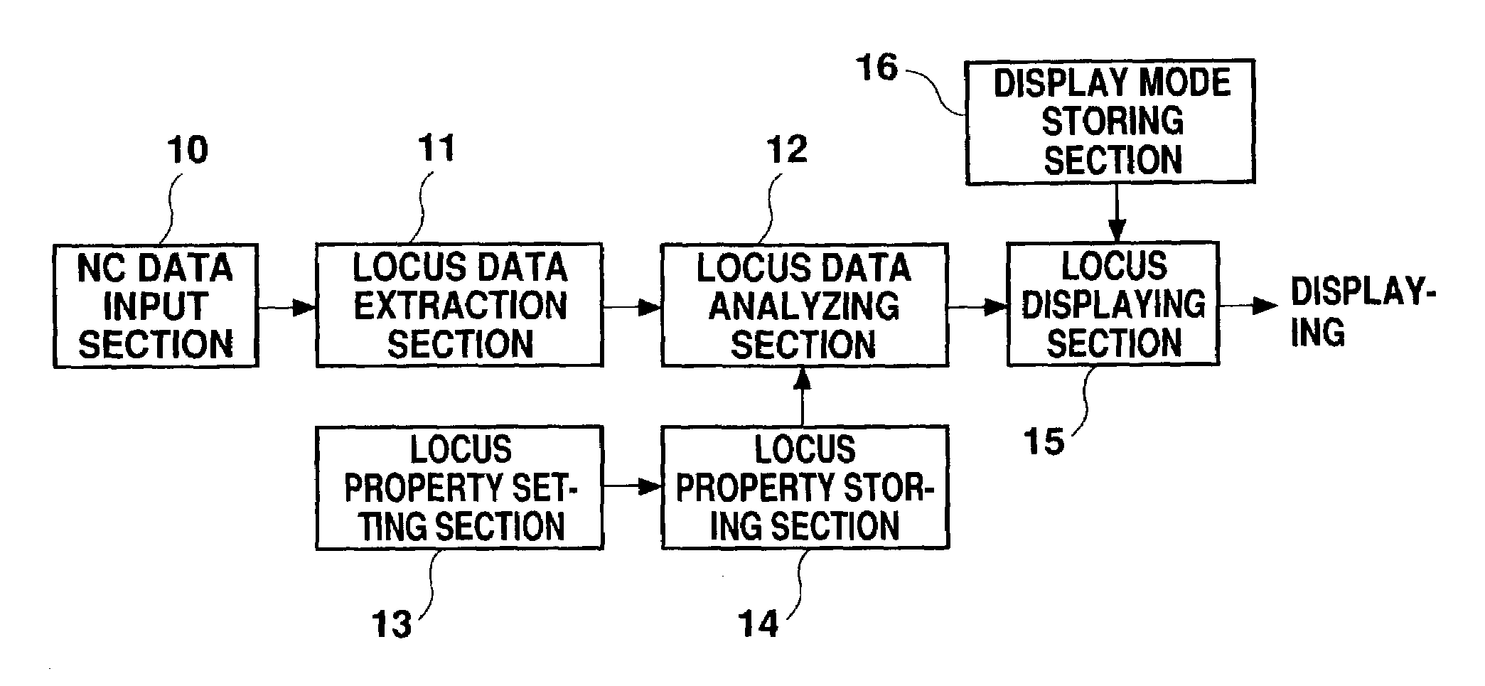
[0064]FIG. 5 is a block diagram showing a display device for performing a display method according a first embodiment of the present invention. XYZ axial data is input from an NC data input section 10, and sent to a locus data extraction section 11. In the locus data extraction section 11, only tool locus data is extracted from the XYZ axial data to thereby eliminate other control data. The extracted tool locus data is supplied to a locus data analyzing section 12, where desired display property is imparted thereto, which is characteristic in this embodiment.

[0065]This embodiment is characterized in that a curvature radius of a tool locus at each of two or more NC data points extracted from a group of dots together representing the tool locus is obtained, and that display property is assigned to the point according to the magnitude of the obtained curvature radius, so that the point itself and its relationship to surrounding points are displayed with the assigned display property.

[0...

embodiment 2

[0094]FIG. 15 is a block diagram showing a display device for performing a display method according to a second embodiment of the present invention. XYZ axial data is all input from an NC data input section 10, and sent to a locus data extraction section 11. In the locus data extraction section 11, only tool locus data is extracted from the XYZ axial data to thereby eliminate other control data. The extracted tool locus data is supplied to a locus data analyzing section 12, where desired display property is imparted thereto, which is characteristic in this embodiment.

[0095]This embodiment is characterized in that a movement direction of each minute segment relative to a specific axis, e.g., Z-axis, selected from the three axes is evaluated to determine if the movement directs in a negative, positive, or zero direction, and that different display property is imparted according to the determined direction. This arrangement allows discriminative displaying of concave or convex of a too...

embodiment 3

[0128]In the following, a third preferred embodiment will be described with reference to the attached drawings.

[0129]FIG. 22 is a block diagram showing a display device for practicing a display method according to this third embodiment. XYZ axial data is all input from an NC data input section 10, and sent to a locus data extraction section 11. In the locus data extraction section 11, only tool locus data is extracted from the XYZ axial data to thereby eliminate other control data. The extracted tool locus data is supplied to a locus data analyzing section 12, where desired display property is imparted thereto; this is a characteristic of this embodiment.

[0130]This embodiment is characterized in that a region relative to a specific axis, i.e., the Z-axis, selected from three axes is divided into divided regions for every predetermined width, first beginning with a desired reference point, and that each of the resultant divided regions is given a different predetermined display prope...


PUM


Abstract

With respect to two or more NC data points among a group of dots together representing a tool locus, a curvature radius of the tool locus is determined. Then, the NC data point and its succession with other points is displayed in a display color determined according to the magnitude of the curvature radius. Alternatively, a movement direction of each minute segment relative to a specific axis selected from the three (XYZ) axes is determined as either positive, negative, or zero, and the minute segment or an end point thereof is display with the display property determined according to the movement direction. Still alternatively, after a specific axis is selected from the three (XYZ) axes, a region relative to the selected region is divided along the selected axis, for predetermined dividing width, first beginning with a predetermined reference point, and the resultant divided regions are given predetermined display properties. Then, a tool locus is displayed in the three-axial (XYZ) system according to the display properties given to the respective divided regions.

Description

BACKGROUND OF THE INVENTION[0001]1. Field of the Invention[0002]The present invention relates to a method for displaying a tool locus defined by NC data, and in particular to an improved method for displaying a tool locus defined by NC data for machining a surface having any shape, as successive dots aligned at a minute interval.[0003]The present invention also relates to an improved method for displaying a tool locus defined by NC data for machining along minute segments defined in an XYZ-axial system, as a collection of minute segments or end points attached thereto.[0004]The present invention further relates to an improved method for displaying based on data defined in five-axial system which additionally comprises A and B rotary axes.[0005]2. Description of the Related Art[0006]For machining a surface having a complicated shape, including die machining, NC-controlled machining is employed in a wide range of machining applications. For example, by using NC data prepared in CAD / CA...

Claims


Application Information

Patent Timeline
Patent Type & Authority Patents(United States)
IPC IPC(8): G05B19/406G06F19/00G05B19/4068
CPCG05B19/4068G05B2219/35342G05B19/18
Inventor HASEBE, TAKAOYAMAMOTO, TOORUITOU, NORIYOSHIKATO, TAKUYA
Owner OKUMA CORP
Why Eureka
Try Eureka