
Automated generation of dynamic data entry user interface for relational database management systems

Inactive Publication Date: 2006-06-13
ADVANCED DYNAMIC INTERFACES
View PDF24 Cites 1567 Cited by
  • Summary
  • Abstract
  • Description
  • Claims
  • Application Information

AI Technical Summary

Benefits of technology

[0023]It is the primary object of the present invention to provide a method and system by which data entry forms for relational databases may be generated dynamically at run-time without the necessity of writing computer code to accomplish this task.
[0024]It is a further object of the present invention to provide a method and system by which end users may conveniently navigate through a relational database for the purposes of entering and maintaining data.

Problems solved by technology

But while relational database management systems provide an attractive way to organize and store data, they do not provide a convenient method to accept input from an end user for the purpose of populating the database with information.
However, a myriad of business problems cannot be solved with existing commercial computer systems.
Many business problems are specific to a particular organization requiring a custom database structure to properly model each problem.
Creating custom user interfaces for relational databases is a time consuming and costly process.
For small scale databases with approximately 25 or fewer tables, this process often requires a couple hundred hours of programming effort in addition to numerous resources necessary to gather requirements, test and deploy the system.
For larger databases, the cost increases nearly in direct proportion with the size of the database.
Needless to say, the cost of developing custom user interfaces is extremely expensive often prohibiting the development of such systems for many organizations.
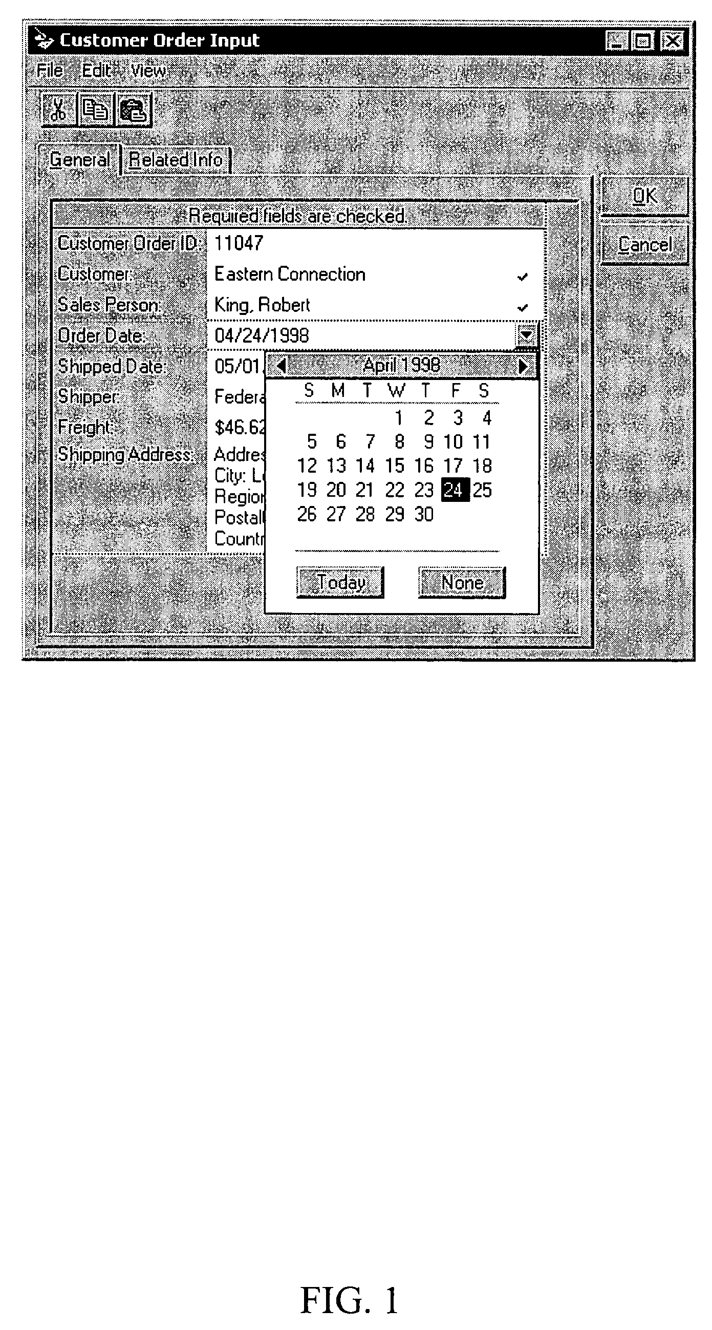
A key problem arises with the form-based user interface depicted above in that if a new data element (i.e., field) is added to a table in the database, a new data entry control must be added to the table's corresponding form in the user interface.
This modification requires further programming effort, additional testing, and a recompilation and redeployment of the user interface.
So not only is the user interface extremely expensive to develop in the first place, it is also very costly to maintain over the lifetime of the database.

Method used


Image

  • Automated generation of dynamic data entry user interface for relational database management systems
  • Automated generation of dynamic data entry user interface for relational database management systems
  • Automated generation of dynamic data entry user interface for relational database management systems

Examples


Embodiment Construction

[0116]As alluded to above, the high cost of developing and maintaining data entry user interfaces in the prior art is largely attributed to the tight coupling of data entry forms with the structure of the underlying relational database. This problem is further aggravated by the common practice of hard coding navigation, business rules and Structured Query Language (SQL) into the source code of the user interface, thus requiring a recompilation and redeployment of the user interface software when modifications to the database structure and / or changes to business logic are made.

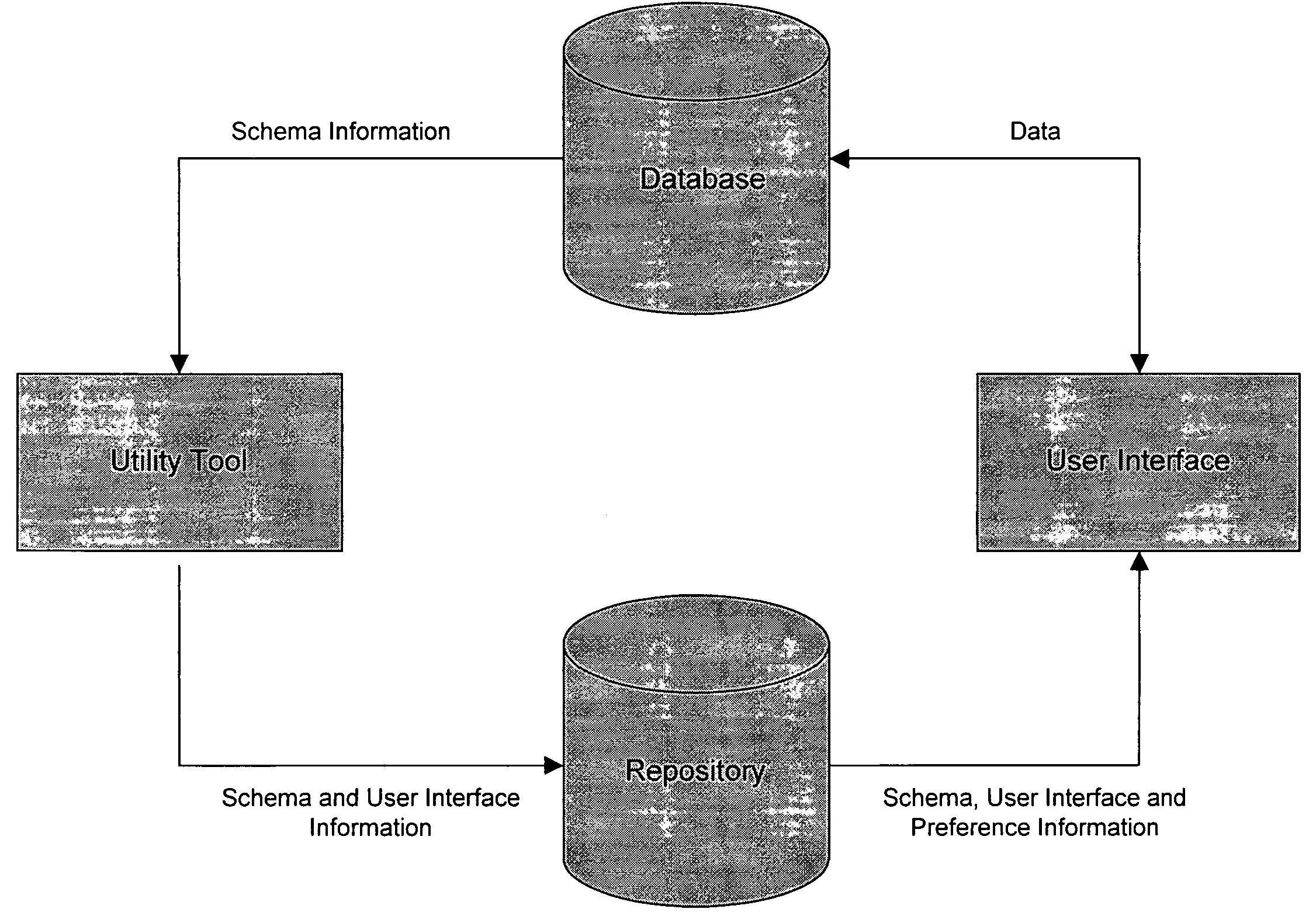
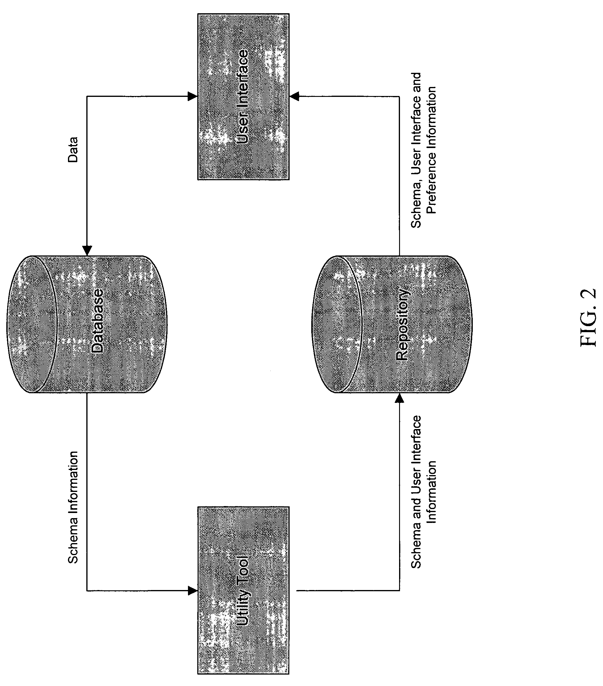
[0117]To overcome this problem, the present invention proposes the high level architecture depicted in FIG. 2. Under this architecture, a utility program (the “Utility Tool”) interprets database schema information from the relational database. Information gleaned from the schema is used to populate a configuration repository with metadata. This metadata is then utilized by the user interface (the “UI”) to: (1) ...


PUM


Abstract

Computer software for, computer apparatus for, and a method of automatically generating a user interface for a relational database comprising extracting schema information from the relational database and automatically generating corresponding schema and user interface metadata, storing the metadata in a repository, and automatically developing from the metadata a user interface appropriate to the relational database.

Description

COPYRIGHTED MATERIAL[0001]A portion of the disclosure of this patent document contains material that is subject to copyright protection. The owner has no objection to the facsimile reproduction by anyone of the patent document or the patent disclosure, as it appears in the Patent and Trademark Office patent file or records, but otherwise reserves all copyrights whatsoever.BACKGROUND OF THE INVENTION[0002]1. Field of the Invention (Technical Field)[0003]The present invention relates to computer database systems and more particularly to a data entry user interface used to populate a relational database with information.[0004]2. Background Art[0005]A glossary is presented in the GLOSSARY OF TERMS section below to facilitate a better understanding of the terms relevant to the present invention. Such terms are denoted by the use of italics.[0006]Relational database management systems are well known in the prior art. A key characteristic of such systems is that data is organized and store...

Claims


Application Information

Patent Timeline
IPC IPC(8): G06F17/00
CPCG06F17/30286G06F16/252Y10S707/99935Y10S707/99934Y10S707/954Y10S707/99945Y10S707/99944Y10S707/99943Y10S707/99942
Inventor KESLER, JOHN N.
Owner ADVANCED DYNAMIC INTERFACES
Learn More