Liquid-cooled valve seat ring
- Summary
- Abstract
- Description
- Claims
- Application Information
AI Technical Summary
Benefits of technology
Problems solved by technology
Method used
Image

Examples
Embodiment Construction
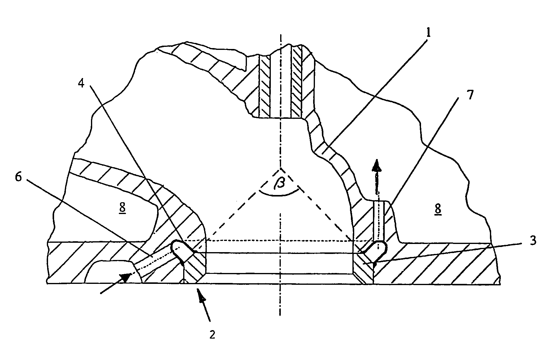
[0016]Referring in detail to the drawings, FIG. 1 shows a cooled valve seat ring 2, consisting of a valve seat part 3 and a sheet-metal cooling channel 4 welded onto the valve seat part, is connected with a cylinder head 1 by means of a laminate casting process.
[0017]The ring space 5 formed by the sheet-metal cooling channel is connected with a coolant circuit by way of bores 6 and 7.
[0018]The valve seat part 3 has a bevel that is characterized by a cone angle beta. The sheet-meal cooling channel 4 covers the valve seat part 3 in the region of this bevel.
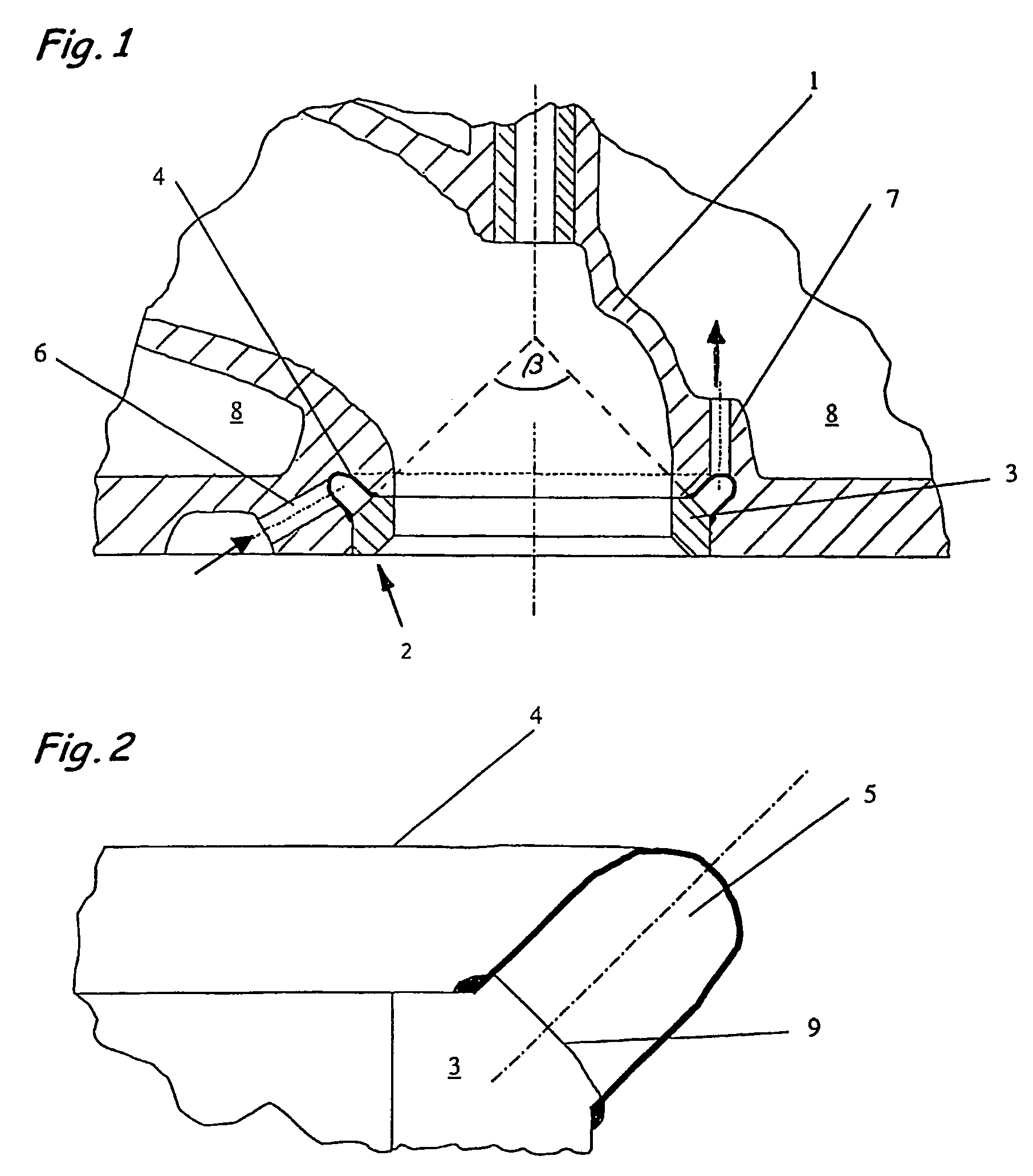
[0019]According to FIG. 2, the valve seat part 3 has centering projections 9 that fix the sheet-metal cooling channel 4 in place on the valve seat part 3 during the welding process.
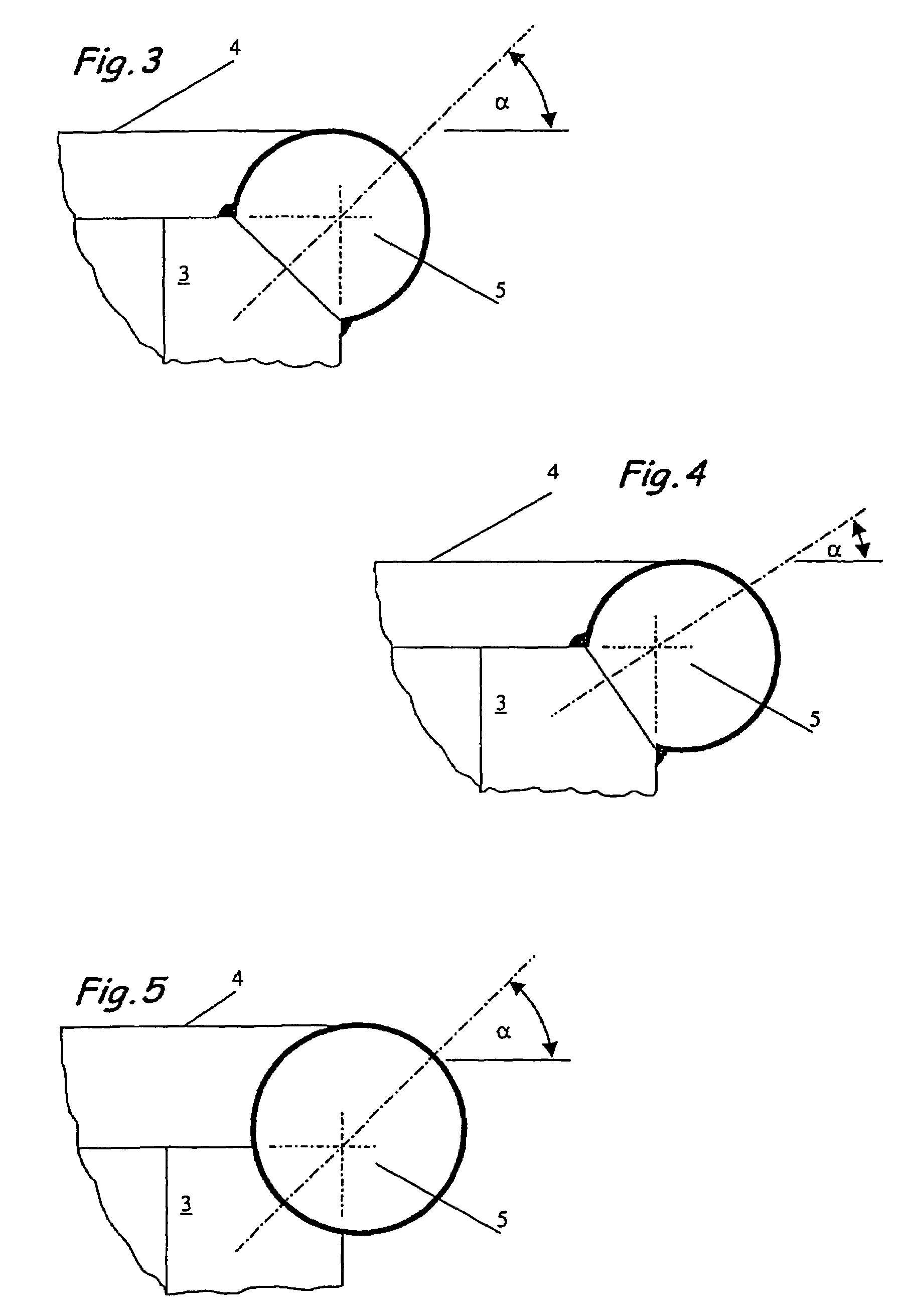
[0020]FIG. 3 shows a cut-out of a valve seat ring having a cooling channel welded on, in cross-section, which is configured as a pipe-shaped component having an open side that faces the seat ring, whereby the sheet-metal channel is joined to the valve sea...
PUM
 Abstract
Description
Claims
Application Information
 - Generate Ideas
- Intellectual Property
- Life Sciences
- Materials
- Tech Scout
- Unparalleled Data Quality
- Higher Quality Content
- 60% Fewer Hallucinations
Browse by: Latest US Patents, China's latest patents, Technical Efficacy Thesaurus, Application Domain, Technology Topic, Popular Technical Reports.
© 2025 PatSnap. All rights reserved.Legal|Privacy policy|Modern Slavery Act Transparency Statement|Sitemap|About US| Contact US: help@patsnap.com