Motor-driven rotary tool with internal heating temperature detecting function

a technology of internal heating temperature and rotary tools, which is applied in the direction of manufacturing tools, portable power-driven tools, drilling pipes, etc., can solve the problems of increasing the degree of inflammation of the surface and interior of the contact skin, the risk of a so-called low-temperature burn, and the increase of the contact tim

Inactive Publication Date: 2006-06-20
TOTSU KATSUYUKI
View PDF17 Cites 13 Cited by
  • Summary
  • Abstract
  • Description
  • Claims
  • Application Information

AI Technical Summary

Benefits of technology

[0010]a temperature sensor is installed in the casing or the like of the electric motor housed within the holding part, and when the temperature of the casing or the like reaches 55° C. to 75° C. or higher as

Problems solved by technology

However, in this type of motor-driven rotary tool, when the operator continuously uses the electric motor for a long time during manual labor, the electric motor heats and the temperature increase of the casing or the like is transmitted to the holding part of the motor-driven rotary tool, thereby risking a so-called low-temperature burn caused by the inflammation that reaches the surface and interior of the skin of the operator's hand.

Method used


Image

  • Motor-driven rotary tool with internal heating temperature detecting function
  • Motor-driven rotary tool with internal heating temperature detecting function
  • Motor-driven rotary tool with internal heating temperature detecting function

Examples


Embodiment Construction

[0025]Next, an embodiment of a motor-driven rotary tool equipped with the internal heating temperature detection function of the present invention will be explained in detail, with reference to the appended drawings.

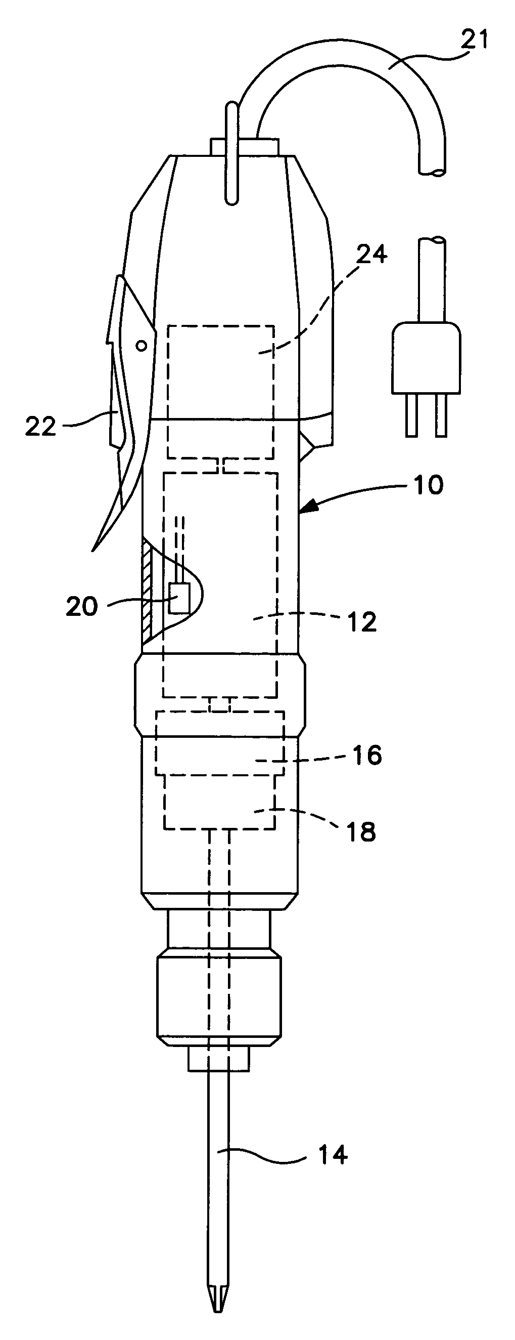
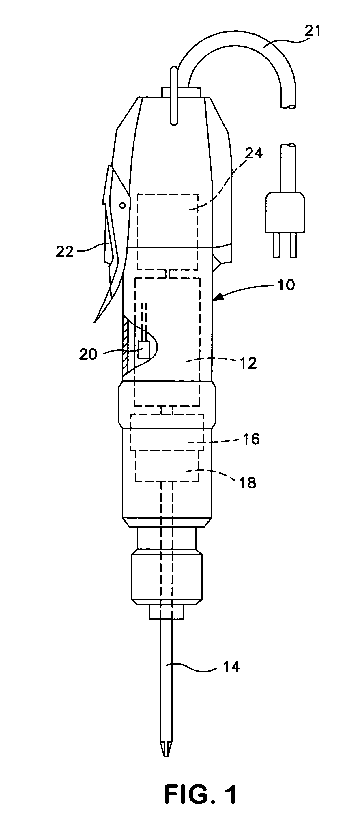
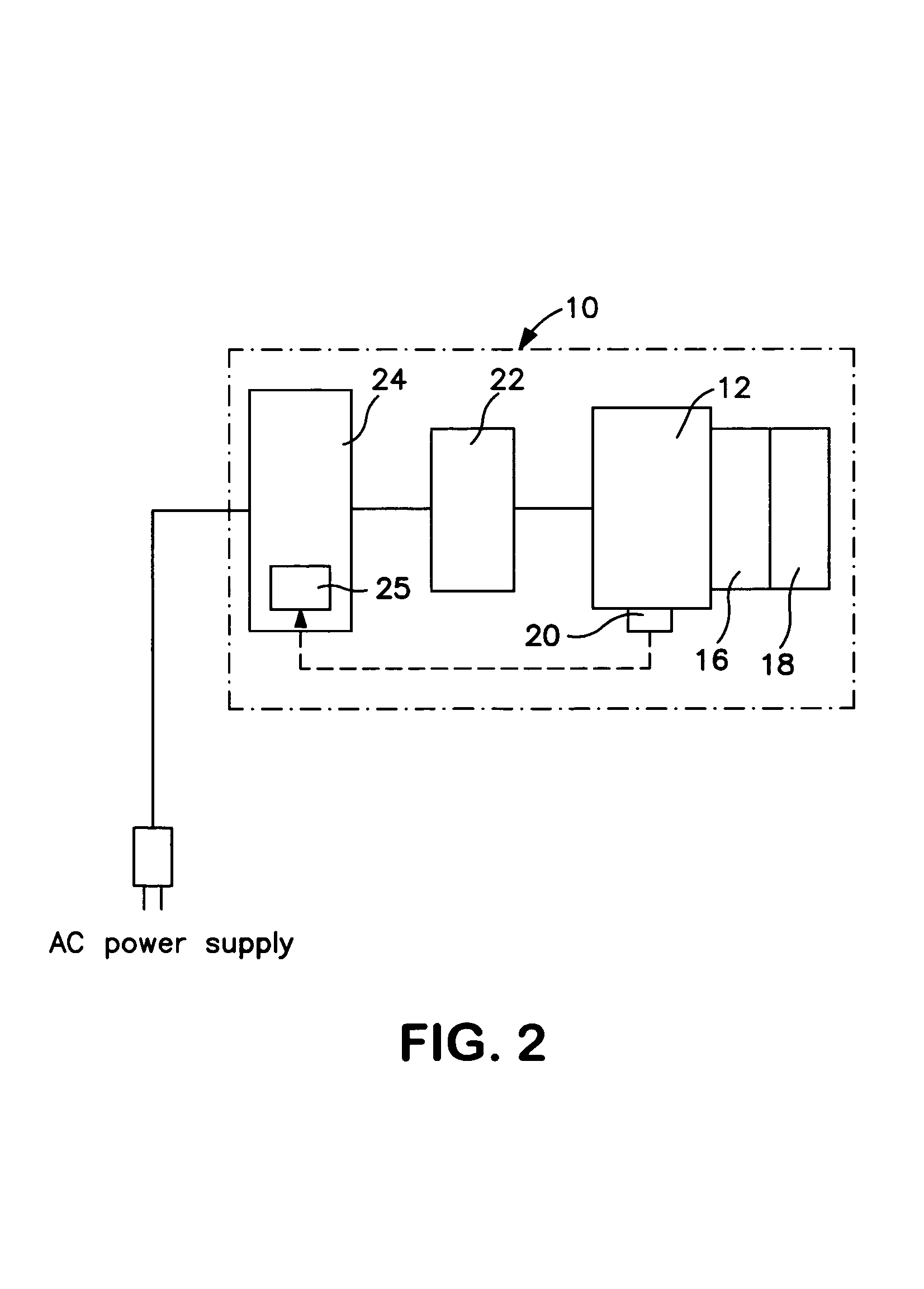
[0026]FIG. 1 shows one embodiment of a motor-driven rotary tool equipped with the internal heating temperature detection function of the present invention. That is, in FIG. 1, reference symbol 10 indicates the holding part of the motor-driven rotary tool, and the electric motor 12 is housed within this holding part 10, and the rotary tool 14 (e.g., a driver bit) installed at the tip of the aforementioned holding part 10 is driven by the driving of this electric motor 12, thereby performing such operations as screw-tightening.

[0027]In this case, deceleration means 16, which is composed of a planetary gear mechanism, for example, is provided on the output shaft of the aforementioned electric motor 12. Furthermore, between this deceleration means 16 and the aforementioned r...


PUM


Abstract

An electric motor-driven rotary tool with an elevated temperature detection function, provided by a temperature sensor, connected to a power shut off device, for shutting off power to the tool, in order to prevent injury, such as low temperature burn, from occurring to an operator of the tool, due to heating of the electric motor, encased in a housing having a holding part for the motor-driven rotary tool, causing an increase of the temperature of the housing, especially the holding part of the tool thereon, to a temperature capable of causing such burn injury to the operator of the tool. The motor-driven rotary tool, includes the electric motor in the housing therefor, the electric motor being for driving workpieces, such as a screwdriver, attached to the motor, for performing operations such as screw tightening; a torque setting and automatic stopping device for detecting a load torque generated in the rotary tool after the specified operations are completed, and for stopping the driving of the rotary tool when the load torque reaches a preset torque value; a temperature sensor installed in the housing of the electric motor for measuring an increase in the temperature of the housing, especially the holding part; and a power shutdown device for detecting a heated state of the housing by the temperature sensor, and shutting off power to the motor when the temperature of the housing increases to at least 55° C. due to heat generated by the electric motor.

Description

BACKGROUND OF THE INVENTION[0001]The present invention relates to a motor-driven rotary tool (e.g., an electric screwdriver) driven by an electric motor, and particularly relates to a motor-driven rotary tool equipped with an internal heating temperature detection function that is configured such that, when the electric motor housed within the holding part is used continuously over an prolonged period, to prevent injury (e.g., low-temperature burn) to the operator as the result of the increase in the temperature at the holding part of the motor-driven rotary tool resulting from the heating of the electric motor, a temperature sensor is provided in the casing, or the like of the electric motor to detect an abnormal temperature increase in the casing, or the like as the result of the heating of the electric motor and to then shut down the power-supply circuit of the electric motor, thereby stopping the driving of the motor-driven rotary tool.[0002]Conventionally, as a motor-driven rot...

Claims


Application Information

Patent Timeline
IPC IPC(8): B23Q5/28B25B21/00B25B23/14B25B23/147B25F5/00
CPCB25B21/00B25F5/008B25B23/14
Inventor TOTSU, KATSUYUKI
Owner TOTSU KATSUYUKI
Why Eureka
Try Eureka