Stent devices with detachable distal or proximal wires

Inactive Publication Date: 2006-06-20
STRYKER EURO OPERATIONS HLDG LLC +1
View PDF49 Cites 129 Cited by
  • Summary
  • Abstract
  • Description
  • Claims
  • Application Information

AI Technical Summary

Benefits of technology

[0013]These and other embodiments of the subject invention will readil

Problems solved by technology

Further, none describe a self-forming stent which forms a tubular structure of turns from a substantially linear

Method used


Image

  • Stent devices with detachable distal or proximal wires
  • Stent devices with detachable distal or proximal wires
  • Stent devices with detachable distal or proximal wires

Examples


Embodiment Construction

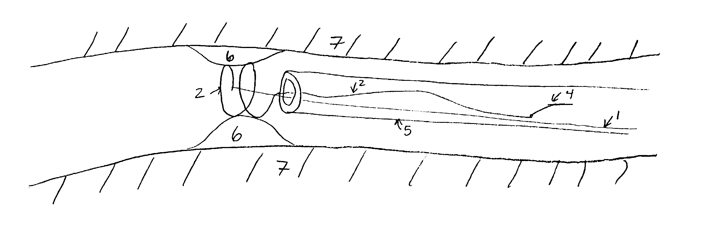
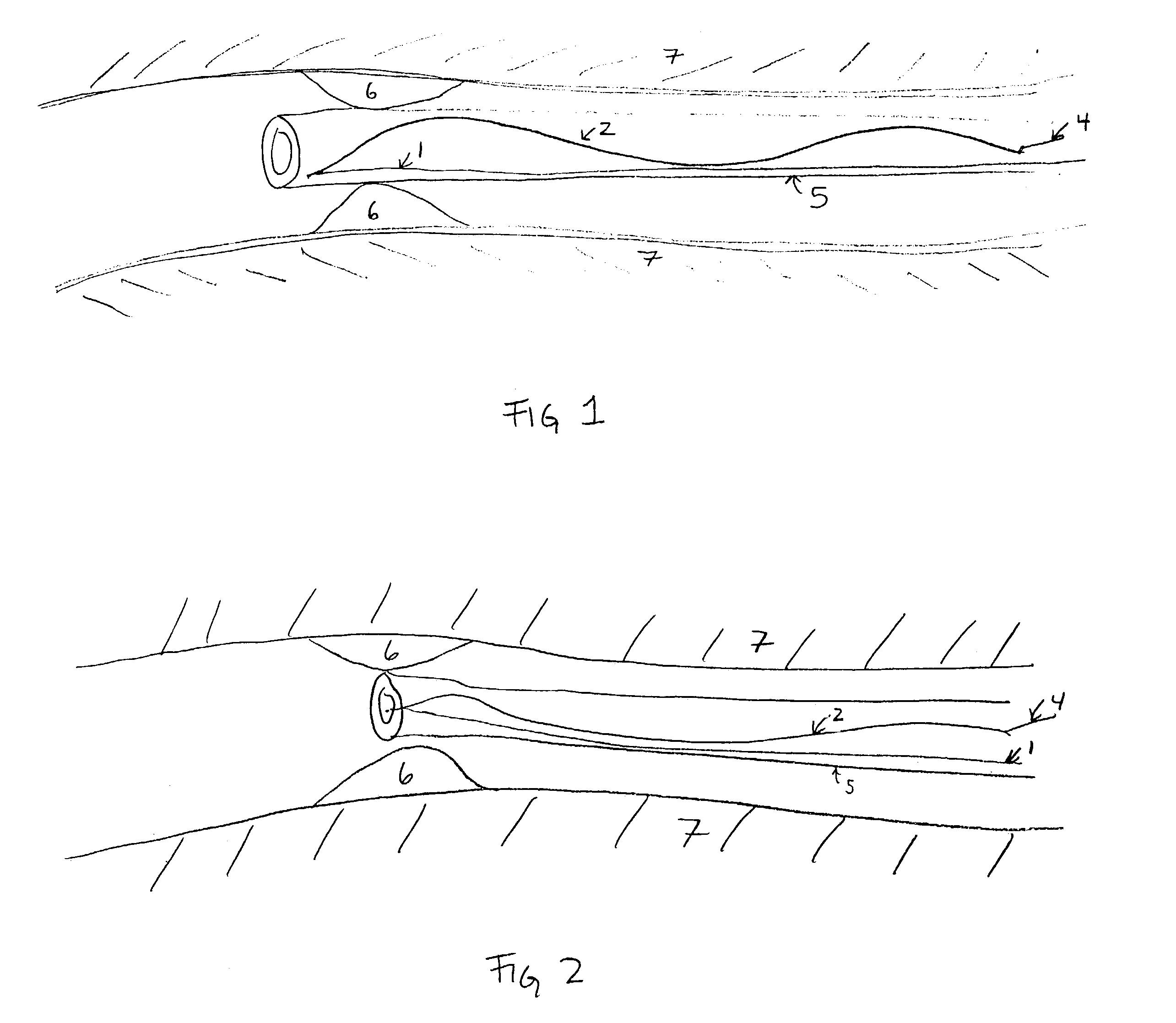
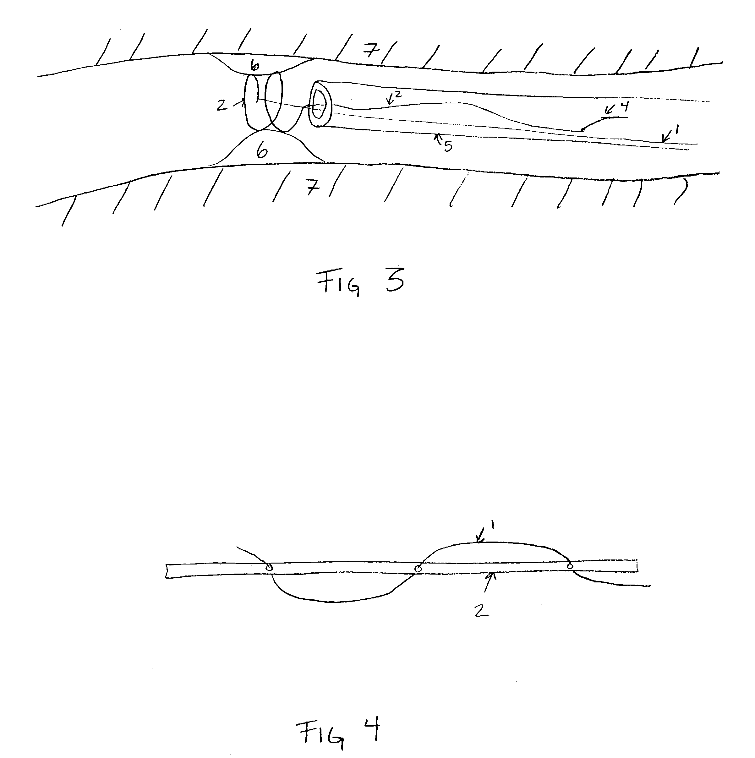
[0018]The present invention includes self-forming or self-expandable stent devices comprising one or more distal wires and / or one or more proximal wires detachably connected to the ends of the stent device. The wires allow the operator to manipulate the position and final configuration of the stent upon deployment. Stent delivery systems (e.g, including inventive stents described herein including proximal and distal wires and a catheter) and methods of using the stents and stent delivery systems are also included in the present invention.

[0019]In one aspect, the stent comprises a self-expandable stent device with attached proximal and / or distal wires. Self-expandable stents are, as described, for example, in U.S. Pat. No. 6,042,597; U.S. Pat. No. 4,655,771 to Wallensten, U.S. Pat. No. 4,954,126 to Wallensten and U.S. Pat. No. 5,061,275 to Wallensten et al. and references cited therein. Thus, in some embodiments the stent with attached delivery wires does not require a balloon or oth...


PUM


Abstract

Stent and stent delivery system suited for the noninvasive treatment of aneurysms, diseased blood vessels, and other bodily lumen are described. Detachable proximal and/or distal wires connected to the proximal and distal ends, respectively, of the stent allow the operator to manipulate the position and final configuration of the stent upon deployment.

Description

[0001]This application is a continuation of patent application Ser. No. 09 / 724,731 filed Nov. 28, 2000 now U.S. Pat. No. 6,579,308, from which priority is claimed under 35 USC §120, and which is incorporated herein by reference in its entirety.FIELD OF THE INVENTION[0002]This invention is a stent and stent delivery system suited for the noninvasive treatment of aneurysms, diseased blood vessels, and other bodily lumen. Unlike most known stents, the stents described herein are able to be positioned in situ with one or more wires attached to at least one location at the distal end of the stent and / or at least one location at the proximal end of the stent.BACKGROUND[0003]This invention is an stent and stent delivery system which may be used within various portions of the body's vasculature. In general, stents are prosthetic devices which may be introduced into a body cavity such as the lumen of a blood vessel or in some other difficult to access location. Stents are particularly useful...

Claims


Application Information

Patent Timeline
IPC IPC(8): A61F2/06A61F2/88A61F2/84
CPCA61F2/88A61F2/95A61F2/962
Inventor JANSEN, LEX P.NITA, HENRYORTIZ, JOHN E.
Owner STRYKER EURO OPERATIONS HLDG LLC
Why Eureka
Try Eureka