Infrared defect detection via broad-band acoustics

a broad-band acoustic and infrared technology, applied in the field of infrared defect detection via, can solve the problem that the single frequency substantially limits the ability to inspect the entire structur

Active Publication Date: 2006-06-20
RAYTHEON TECH CORP
View PDF14 Cites 20 Cited by
  • Summary
  • Abstract
  • Description
  • Claims
  • Application Information

AI Technical Summary

Problems solved by technology

Unfortunately, the use of a single frequency substantia

Method used


Image

  • Infrared defect detection via broad-band acoustics
  • Infrared defect detection via broad-band acoustics
  • Infrared defect detection via broad-band acoustics

Examples


Embodiment Construction

)

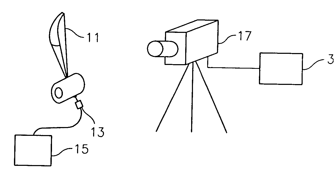
[0019]It is a central purpose of the present invention to provide an apparatus and means for using the apparatus to detect defects in parts, in particular machined parts, using infrared detection of mechanical energy induced via broad-band acoustic excitation. In a preferred embodiment, the method of the present invention is applied to the detection of defects in fan blades, compressor blades, and gas turbines, particularly those fabricated from nickel titanium, steel, and titanium alloys. The infrared detection is facilitated by introducing broad-band acoustic energy into the part. The introduced energy causes an increase in temperature in and around the source of structural defects which may be visually detected using infrared imaging equipment. Subsequent images may then be image processed in real time to display an output image. The specifics of how this detection is accomplished is described in greater detail below.

[0020]With reference to FIG. 1, there is illustrated the defec...


PUM


Abstract

A method of detecting defects in structures, comprising the steps of inducing mechanical energy in a structure via the emission of a broad-band acoustic signal, and capturing over a time interval a plurality of images of the structure each of the plurality of images comprised of a plurality of pixels arranged in a plurality of rows and columns each indicative of an intensity of infrared energy emitted by a portion of the structure.

Description

BACKGROUND OF THE INVENTION[0001](1) Field of the Invention[0002]The present invention relates to a method, and apparatus for performing such method, for detecting defects in structures via broad-band acoustic excitation. More specifically, the present invention relates to a method of imparting mechanical energy into a structure via the emission of broad-band acoustic energy and optically recording the subsequent emission of infrared energy from the structure arising from such excitation.[0003](2) Description of Related Art[0004]It is known in the art of defect detection to induce mechanical nature in a structure via the emission of a single frequency acoustic signal. It is then possible to image or otherwise study the structure to detect infrared emissions arising in the structure as the result of such excitation. Unfortunately, the use of a single frequency substantially limits the ability to inspect the entire structure.[0005]What is therefore needed is an apparatus, and a method...

Claims


Application Information

Patent Timeline
IPC IPC(8): G01J5/02G01N21/00G01N21/70G01M99/00G01N25/72G01N29/06G01N29/14G01N29/22G01N29/34G06T7/00
CPCG01N21/70G01N29/06G01N29/348G06T7/0004G01N29/228G01N25/72G06T2207/30164G01N2291/2693G01N29/14
Inventor RAULERSON, DAVIDOUYANG, ZHONGSMITH, KEVIN D.
Owner RAYTHEON TECH CORP
Why Eureka
Try Eureka