Power tools with switched reluctance motor

a technology of reluctance motor and power tool, which is applied in the direction of drilling pipes, woodworking apparatus, association for rectification, etc., can solve the problems of manufacturing tolerances, electrical noise, disassembly and assembly, etc., and achieves enhanced cooling, reduced tolerance stacking, and efficient operation

Inactive Publication Date: 2006-06-20
MILWAUKEE ELECTRIC TOOL CORP
View PDF42 Cites 90 Cited by
  • Summary
  • Abstract
  • Description
  • Claims
  • Application Information

AI Technical Summary

Benefits of technology

[0016]It is an independent advantage of the invention to provide a power tool that is configured to be hand-held during operation that is driven by a switched reluctance motor. It is an independent advantage of the invention to provide a construction that reduces tolerance stack-up. Also, it is an independent advantage of the invention to provide a self-contained electronics package that plugs into a SR motor to provide control functions to the SR motor. In addition, it is an independent advantage of the invention to provide enhanced cooling that keeps the electronics and the components of the SR motor cool for efficient operation. Further, it is an independent advantage of the invention to provide an encapsulated magnet that allows for contaminant free motor control over the life of the SR motor. It is an independent advantage to provide an apparatus and a method for aligning magnet poles of a magnet hub with respect to the rotor poles the magnet poles represent.
[0017]Other independent features and independent advantages of the invention will become apparent to those skilled in the art upon review of the following detailed description, claims, and drawings.

Problems solved by technology

Although SR motors provide a number of benefits over the types of drive units currently used in hand-held power tools, a number of constraints have kept the SR motor from being utilized as a drive unit for such hand-held power tools.
The small space design considerations result in problems when attempting to integrate a SR motor and the electronics associated with the SR motor into a hand-held power tool.
The independent problems include, among others, those associated with heat dissipation, electrical noise, manufacturing tolerances, etc.

Method used


Image

  • Power tools with switched reluctance motor
  • Power tools with switched reluctance motor
  • Power tools with switched reluctance motor

Examples


Embodiment Construction

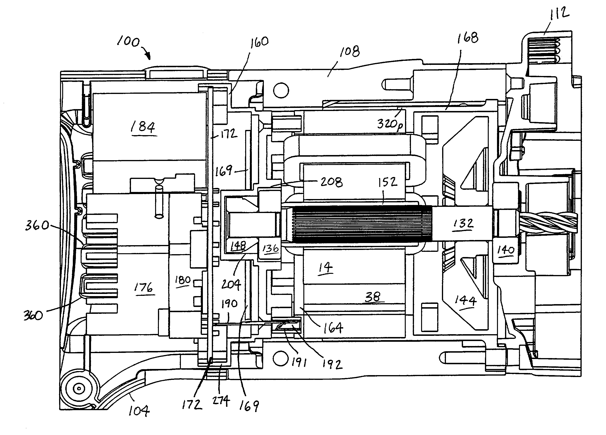
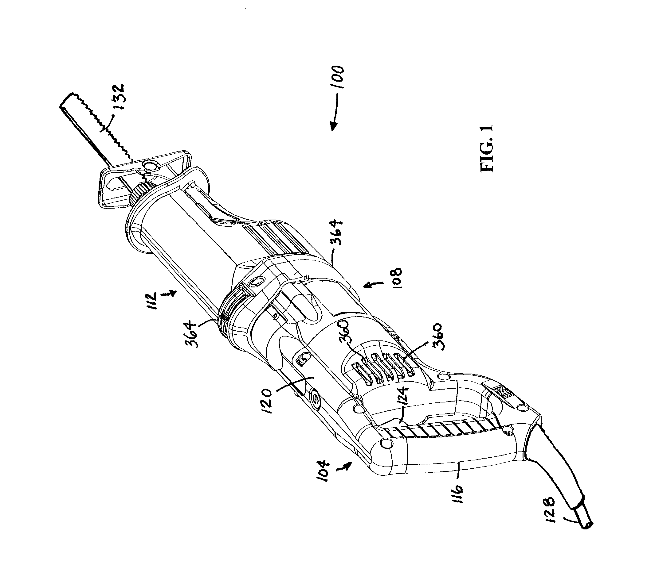
[0048]FIG. 1 illustrates an electrical device 100 embodying aspects of the invention. In the illustrated construction and in some aspects, the electrical device 100 is a power tool, and, more particularly, a power tool configured to be hand-held during operation (i.e., the electrical device 100 is a power tool designed to be supported by an operator, and not normally supported on a surface, such as a workbench, during operation). In the illustrated construction, the electrical device 100 is a reciprocating saw. It should be understood that aspects of the invention apply equally to any electrical device that includes a SR motor, such as, for example other power tools configured to be hand-held during operation (e.g., drills, circular saws, grinders, reciprocating saws, sanders, caulk guns, jigsaws, screwdrivers, heat guns, impact wrenches, shears, nibblers, rotary hammers, routers, hand planers, plate jointers, rotary tools, etc.), power tools not configured to be hand-held during op...


PUM

PropertyMeasurementUnit
rotationaaaaaaaaaa
electricallyaaaaaaaaaa
voltageaaaaaaaaaa

Abstract

A method of assembling a power tool, a power tool, a method of assembling an electrical device, and an electrical device includes a switched reluctance motor. The electrical device is preferably a hand-held power tool, however, any type of electrical device that includes a switched reluctance motor may benefit from any number of aspects of the invention. In one independent aspect, the invention provides a construction that reduces tolerance stack-up. In another independent aspect, the invention provides a self-contained electronics package that plugs into a switched reluctance motor to provide control operation of the switched reluctance motor. In another independent aspect, the invention provides enhanced cooling that increases the efficiency of the electrical device using a switched reluctance motor. In another independent aspect, the invention provides an encapsulated magnet that allows for contaminant free motor control over the life of the SR motor. In another independent aspect, the invention provides an apparatus and a method for aligning magnets of a magnet hub with respect to the rotor poles the magnet poles represent.

Description

RELATED APPLICATIONS[0001]This application claims the benefit of prior filed provisional patent application, Ser. No. 60 / 354,253, filed Feb. 4, 2002, the entire contents of which are incorporated by reference herein.FIELD OF THE INVENTION[0002]The present invention relates to electrical devices that include a switched reluctance (“SR”) motor and, more particularly, to power tools that include a SR motor.BACKGROUND OF THE INVENTION[0003]A typical SR motor includes multiple salient poles on both the stator and the rotor. Windings or coils are wound on the stator poles, and each pair of windings on diametrically opposite stator poles are connected in series or in parallel to form an electrically independent phase of the SR motor. The rotor is made of a magnetically permeable material such as, for example, a ferrous alloy. Electronics are utilized to energize the independent phases of the SR motor which thereby produce a magnetic field that interacts with the rotor poles to turn the rot...

Claims


Application Information

Patent Timeline
Patent Type & Authority Patents(United States)
IPC IPC(8): H02K3/52B23D45/16B25F5/00B27B5/29H02K5/15B23D47/12B23D49/16B23D51/16H02K5/10H02K5/173H02K5/20H02K7/14H02K9/06H02K11/04H02K15/00H02K19/10H02K29/08
CPCB23D45/16B23D49/16B23D51/16B25F5/00B27B5/29H02K3/522H02K5/15H02K7/145H02K9/06H02K11/0073H02K15/00H02K29/08B23D47/12H02K2203/03H02K5/10H02K5/1732H02K5/20H02K19/103H02K11/33H02K5/207H02K11/044H02K11/00H02P25/08
Inventor HEMPE, DAVID A.MEYER, GARY D.EBBEN, RODERICK N.BROZEK, JEFFREY M.
Owner MILWAUKEE ELECTRIC TOOL CORP
Why Eureka
Try Eureka