Dead-time-modulated synchronous PWM controller for dimmable CCFL royer inverter

Inactive Publication Date: 2006-06-20
NAT TAIWAN UNIV OF SCI & TECH
View PDF4 Cites 34 Cited by
  • Summary
  • Abstract
  • Description
  • Claims
  • Application Information

AI Technical Summary

Benefits of technology

[0005]It is therefore an object of the present invention to propose a synchronous DTM-PWM controller to provide energy pump-up to the Royer inverter for dimming the CCFLs.

Problems solved by technology

Major difficulties in regulating the self-oscillating Royer inverter

Method used


Image

  • Dead-time-modulated synchronous PWM controller for dimmable CCFL royer inverter
  • Dead-time-modulated synchronous PWM controller for dimmable CCFL royer inverter
  • Dead-time-modulated synchronous PWM controller for dimmable CCFL royer inverter

Examples


Embodiment Construction

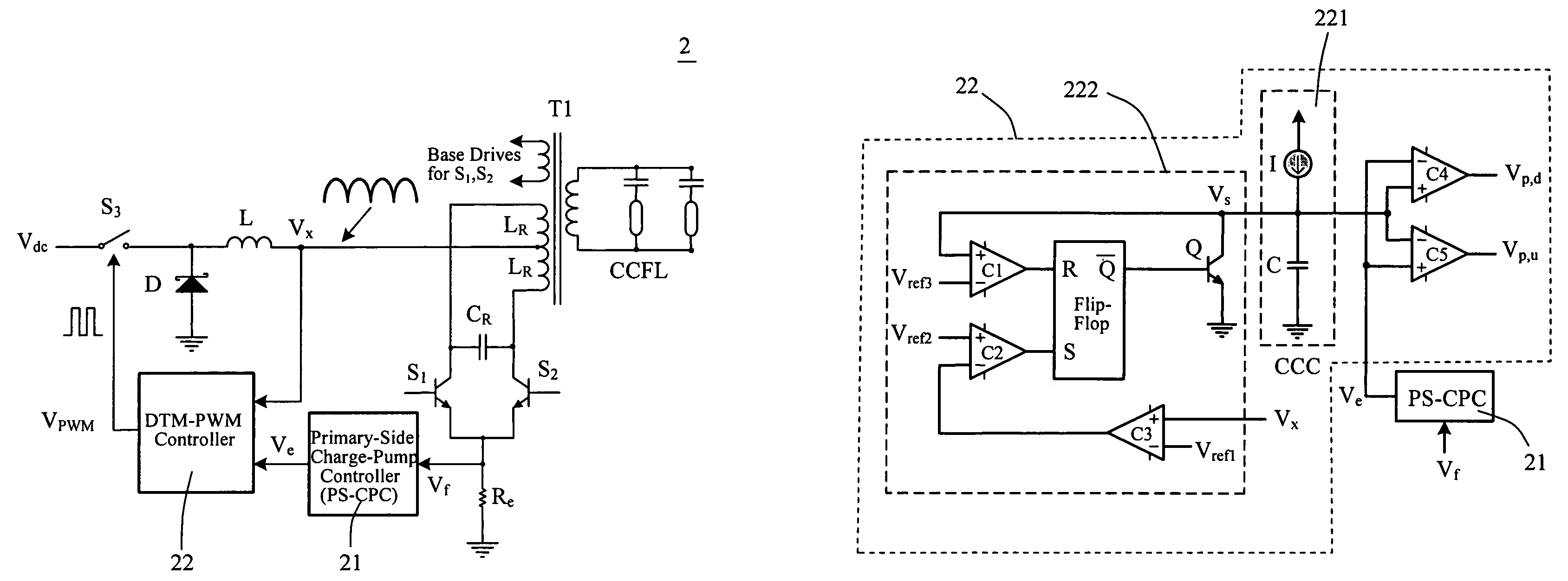
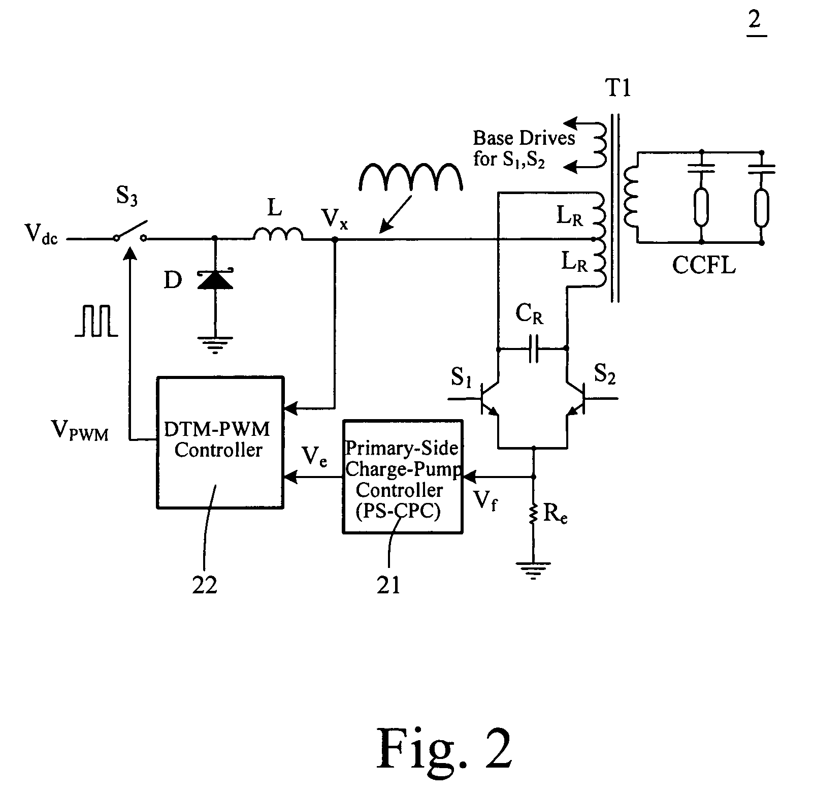
[0047]FIG. 2 shows the schematic circuit diagram of the DTM-PWM controlled Royer inverter 2 of the preferred embodiment of the present invention, in which the primary-side charge-pump controller (PS-CPC) 21 is included (G. C. Hsieh, “Eliminating thermostat effect and dimming ability purposed electronic ballast for CCFL driver system,” ROC Patent No. 175770, 2003-2021).

[0048]The proposed DTM-PWM controller 22 is shown in FIG. 3, which primarily consists of a constant current charger (CCC) 221 and a monostable circuit 222. The CCC 221 having a current source I, and a capacitor C is a linear charger and is designed to produce a DTM sawtooth waveform Vs. The monostable circuit 222 is composed of two comparators (C1 and C2), one RS Flip-Flop, and a discharger Q. The comparator C3 is for the synchronization detection and provides a trigger signal Vt for initiating the monostable circuit 222 when zero voltage or preset threshold voltage (Vref1) is detected at the center tap voltage Vx of t...


PUM


Abstract

A Synchronous PWM controller realized by dead-time modulation is provided for applying to the self-oscillation Royer inverter. The proposed dead-time-modulated PWM (DTM-PWM) controller is composed of a monostable circuit and a constant-current charger (CCC). The presented switching period for the buck regulation consists of a referred sawtooth having a constant-period and a dead-time. The synchronizing strategy is conducted by modulating the dead-time according to the resonant frequency of the Royer inverter. Two kinds of the control strategies in DTM-PWM controller are explored including the down-going and up-going error voltage controls. A DTM-PWM controlled dimmable Royer inverter with two-CCFL having primary-side control is designed and realized. Two kinds of the existing controllers for the Royer inverter are also experimented and compared with the proposed DTM-PWM controller. The results of the analysis and the theoretical prediction are verified with the experiments.

Description

FIELD OF THE INVENTION[0001]The present invention relates to a dead-time-modulated pulse width modulation (DTM-PWM) controller. More specifically, this invention relates to a DTM synchronous PWM controller for dimming a cold-cathode fluorescent lamp (CCFL) Royer inverter.BACKGROUND OF THE INVENTION[0002]Major difficulties in regulating the self-oscillating Royer inverters for driving a CCFL primarily stem from the synchronization problem. Nowadays, lots of synchronization control strategies have been developed for solving the regulation problems on Royer inverters. The general approach to achieve the synchronization is only by modulating the converter center frequency with some degree of variations.[0003]A typical current-fed Royer inverter for CCFL 1 is shown in FIG. 1. In which, the current source is formed by a buck converter 12. Switches S1 and S2 are in self-oscillation with a resonant tank CR and LR. The energy pump-up from the current-fed buck converter12 is controlled by a P...

Claims


Application Information

Patent Timeline
IPC IPC(8): H05B41/16
CPCH05B41/2825Y10S315/04Y02B20/185Y02B20/00
Inventor HSIEH, GUAN-CHYUN
Owner NAT TAIWAN UNIV OF SCI & TECH
Why Eureka
Try Eureka