
Data slicer capable of automatically removing current mismatch between current pumps incorporated therein and its operating method

a data slicer and current pump technology, applied in the field of data slicers, can solve the problems of weak radiation power of the reflected laser beam detected by the optical pick-up head, and achieve the effect of greatly improving the accuracy of the reproduced digital data generated by the data slicer

Active Publication Date: 2006-06-20
MEDIATEK INC
View PDF1 Cites 7 Cited by
  • Summary
  • Abstract
  • Description
  • Claims
  • Application Information

AI Technical Summary

Benefits of technology

[0013]It is an advantage of the claimed invention that the data slicer adjusts the output current of the current pumps to reduce the difference between a first offset value and a second offset value. Therefore, the actual slice reference level is maintained within a predetermined tolerance window so that accuracy of the reproduced digital data generated by the data slicer is greatly improved.

Problems solved by technology

Therefore, the radiation power of the reflected laser beam detected by the optical pick-up head is weaker.

Method used


Image

  • Data slicer capable of automatically removing current mismatch between current pumps incorporated therein and its operating method
  • Data slicer capable of automatically removing current mismatch between current pumps incorporated therein and its operating method
  • Data slicer capable of automatically removing current mismatch between current pumps incorporated therein and its operating method

Examples


Embodiment Construction

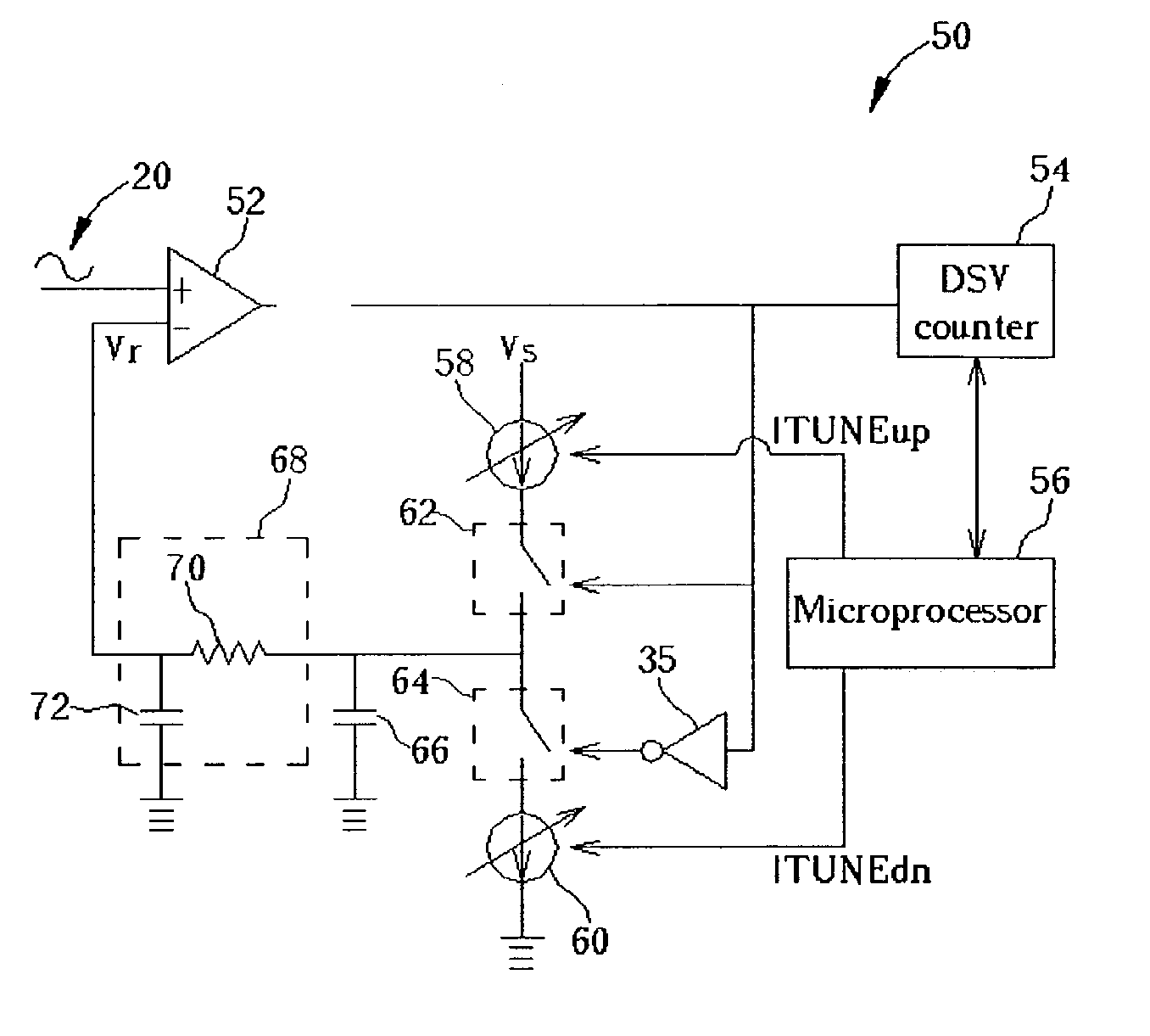
[0023]Please refer to FIG. 6, which is a circuit diagram of a data slicer 50 according to the present invention. The data slicer 50 has a comparator 52, a DSV counter 54, a microprocessor 56, two current pumps 58, 60, two switches 62, 64, a capacitor 66, and a low-pass filter 68 including a resistor 70 and a capacitor 72. One input terminal (non-inverting terminal) of the comparator 52 is used to receive the detecting signal 20 generated by an optical pick-up head, and another input terminal (inverting terminal) is used to receive a slice reference level Vr. The comparator 52 repeatedly compares the detecting signal 20 with the slice reference level Vr to reproduce the original digital data. The DSV counter 54 is used to calculate DSV of the digital data outputted from the comparator 52. That is, when the comparator 52 outputs a high voltage level representing a logic high value (“1” for example), the DSV counter 54 increases the DSV of the digital data outputted from the comparator...


PUM

PropertyMeasurementUnit
voltageaaaaaaaaaa
currentaaaaaaaaaa
timeaaaaaaaaaa

Abstract

A data slicer capable of removing current mismatch between internal current pumps and its operating method is proposed. The data slicer includes a comparator for comparing an analog signal with a slice reference level to convert the analog signal into a digital signal, a counter electrically connected to the comparator for calculating a digital sum value according to logic values carried by the digital signal, and a voltage-adjusting circuit electrically connected to the comparator for adjusting the slice reference level. The voltage-adjusting circuit has two current pumps for shifting the slice reference level. The current generated by the current pumps can be adjusted according to the calculated digital sum value to reduce a difference between a first and a second binary values which are used to increase and decrease the slice reference level respectively.

Description

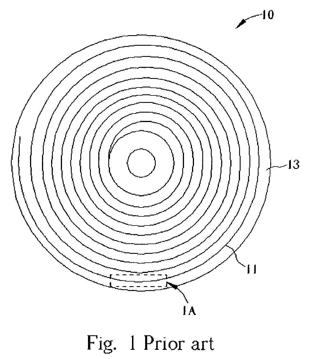
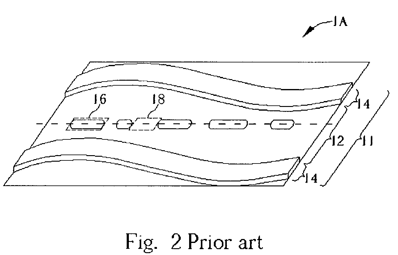
BACKGROUND OF INVENTION[0001]1. Field of the Invention[0002]The present invention relates to a data slicer and its operating method, and more particularly, to a data slicer capable of automatically removing the current mismatch between current pumps incorporated therein and its operating method.[0003]2. Description of the Prior Art[0004]With a rapid development of computer technology, most analog data can be transformed into digital data to facilitate data transmission and storage. In recent years, the use of compact discs (CDs) as a storage medium has been adopted extensively. As a result, optical recorders such as recordable compact disc (CD-R) and rewritable compact disc (CD-RW) drives have entered the mainstream of the electronic product market. A great amount of information can be stored on a compact disc through the use of these optical recorders.[0005]Please refer to FIG. 1 which shows a top view of a typical compact disc 10. As is well known in the art, the compact disc 10 i...

Claims


Application Information

Patent Timeline
Patent Type & Authority Patents(United States)
IPC IPC(8): G11B7/00G11B7/005G11B20/10
CPCG11B7/005G11B20/10009G11B2020/1457
Inventor HUNG, WEI-CHOUPENG, KOU-CHIHLEE, CHIA-CHING
Owner MEDIATEK INC
Learn More