Scatter and beam hardening correction in computed tomography applications

a computed tomography and beam hardening technology, applied in the field of industrial computed tomography (ct) systems, can solve the problems of reducing the accuracy of the computed tomography, requiring extensive added hardware, and producing pronounced artifacts

Inactive Publication Date: 2006-06-20
GENERAL ELECTRIC CO
View PDF15 Cites 23 Cited by
  • Summary
  • Abstract
  • Description
  • Claims
  • Application Information

AI Technical Summary

Problems solved by technology

The phenomenon is significant in computed tomography of industrial parts because the materials, often metallic in nature, scatter x-rays to a greater degree, and is especially deleterious for three-dimensional, volumetric computed tomography where the entire object is irradiated by a cone beam of x-rays.
This spatially-varying background adds to the true signal and can produce pronounced artifacts when the three-dimensional image of the object is mathematically reconstructed.
However, such a method requires extensive added hardware and provides only a coarse grid of scatter estimates.
More importantly, this approach has proven experimentally difficult and unable to provide accurate scatter estimates.
However such estimates are calculation heavy and consume a large amount of processor time, a requirement which is prohibitive where a variety of different complex shape are to be imaged, as is the case in industrial imaging.

Method used


Image

  • Scatter and beam hardening correction in computed tomography applications
  • Scatter and beam hardening correction in computed tomography applications
  • Scatter and beam hardening correction in computed tomography applications

Examples


Embodiment Construction

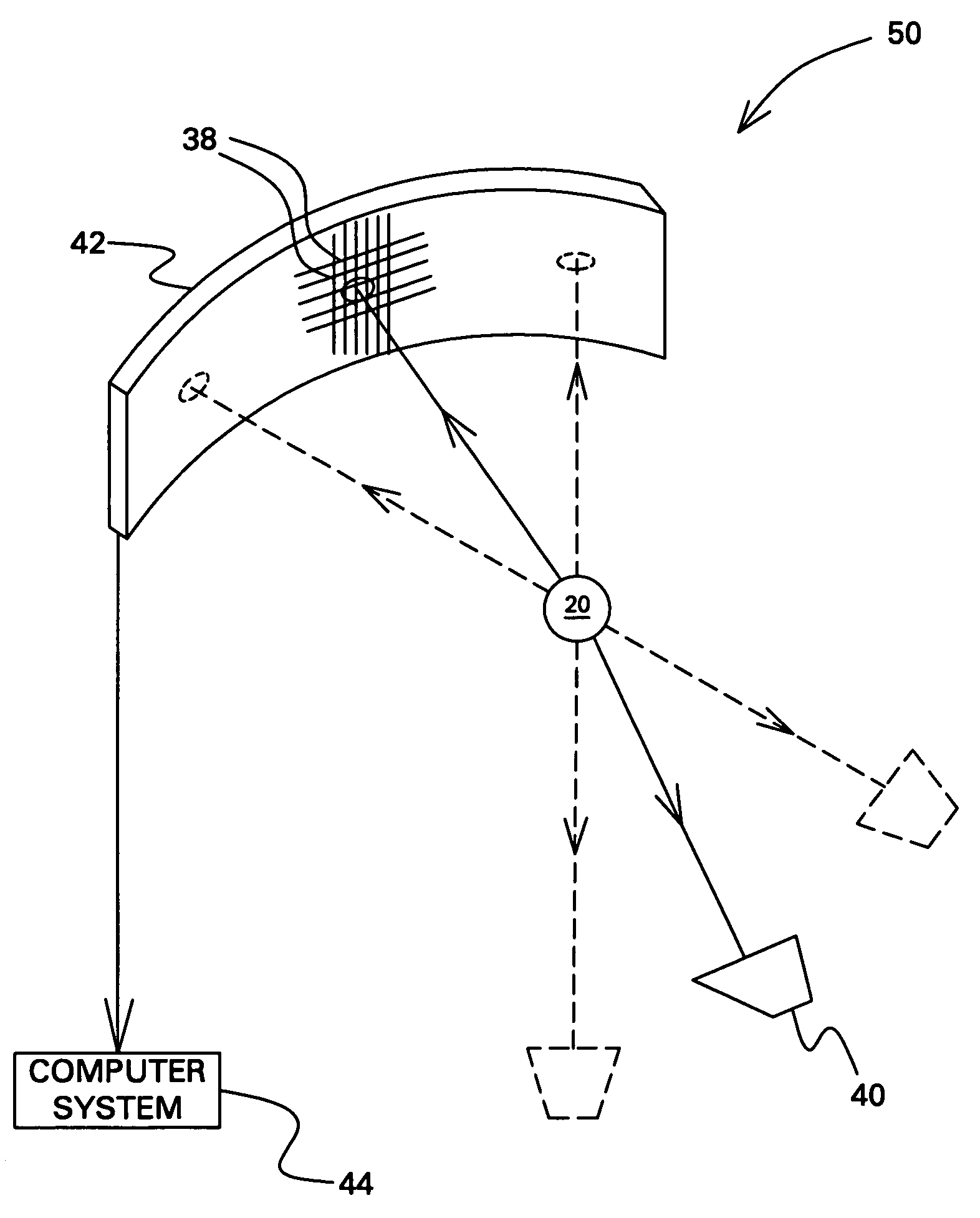
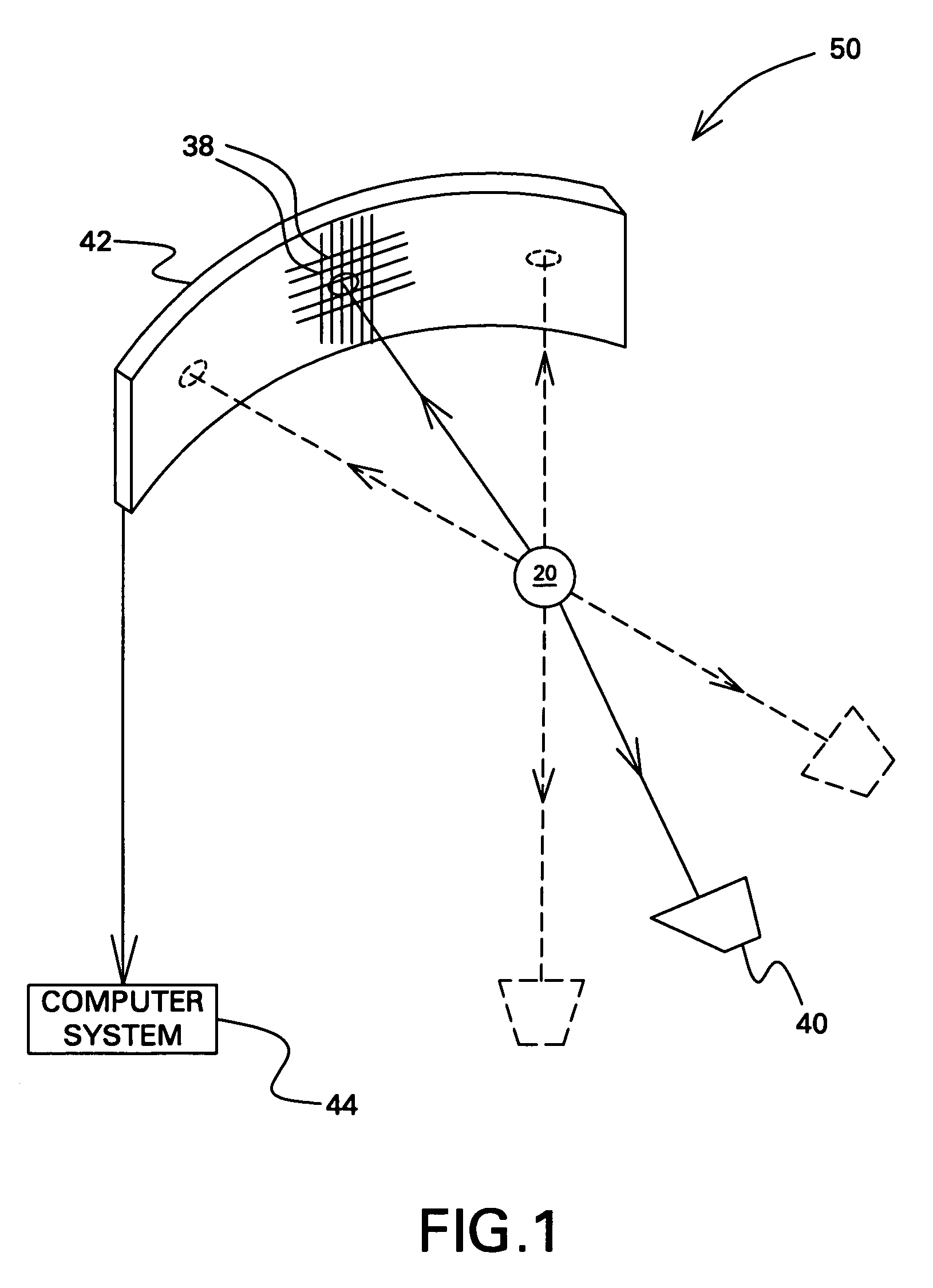
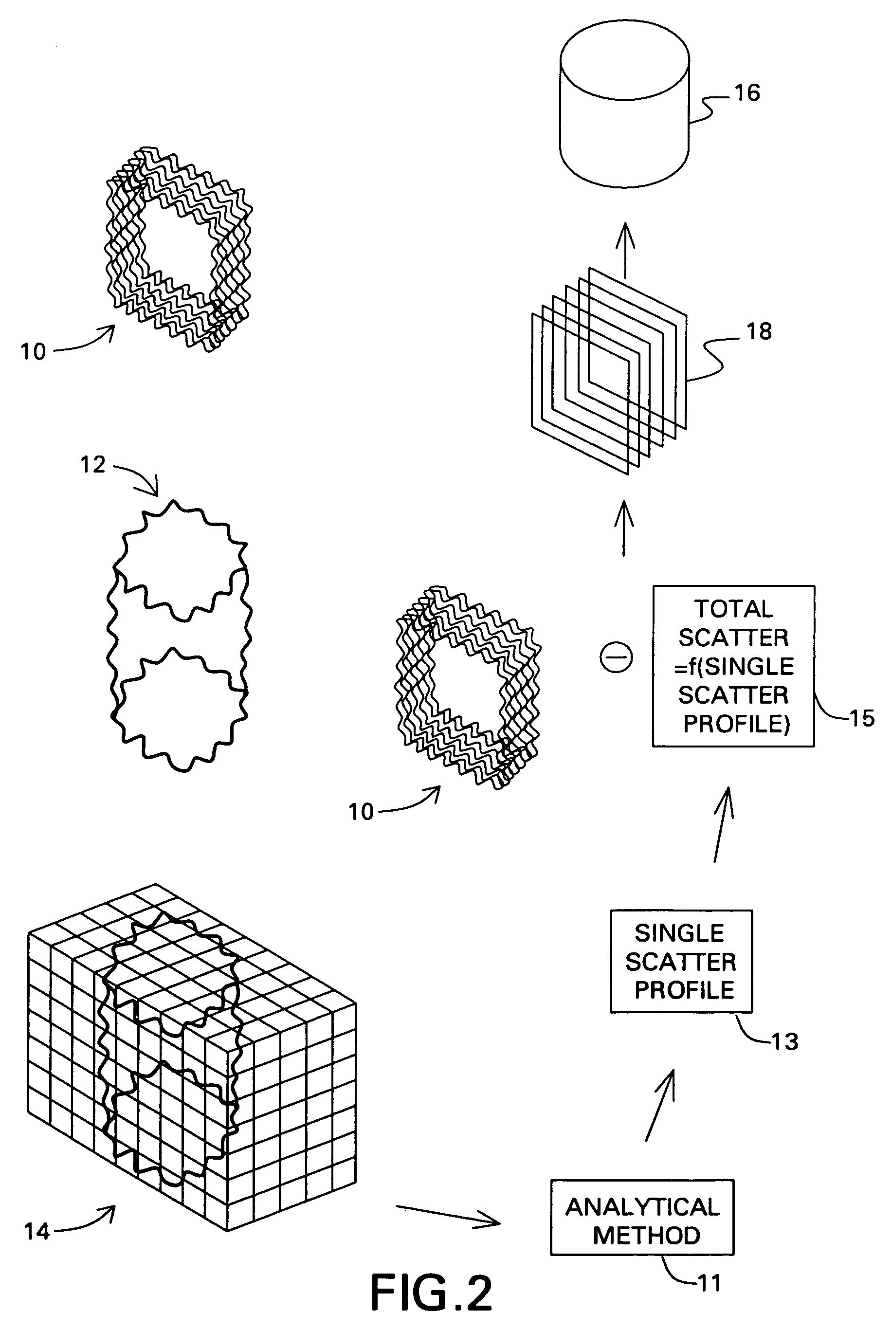
[0019]FIG. 1 shows an imaging system 50 for correcting scatter in an image of an object 20, according to an embodiment of the invention. At least one radiation source 40 is adapted to expose the object 20 to radiation suitable for imaging, for example, x-rays. A detector arrangement 42 is disposed with respect to the radiation source 40 to receive x-rays passing from the radiation source 40 through the object 20. The x-rays passing through the object project a two-dimensional impression, referred to as raw projection data 10, on the detector arrangement 42. A computer system 44 is coupled to the detector arrangement 42 and configured to acquire a set of raw projection data 10 from the detector arrangement 42, to generate a three dimensional (3D) image 12 from the raw projection data 10. The projection data 10 is comprised of a number of projections from different views, depending upon the application, and in some cases this number varies between 180–2500. However the number of proje...


PUM

PropertyMeasurementUnit
CTaaaaaaaaaa
computed tomographyaaaaaaaaaa
widthaaaaaaaaaa

Abstract

A method of correcting scatter includes obtaining a voxellized representation of a 3D image of an object from a plurality of projection data. A single scatter profile for the object is calculated using the voxellized representation of the 3D image of the object. A total scatter profile for the object is determined using the single scatter profile and an adjustment factor and the projection data is corrected using the total scatter profile to obtain a scatter corrected projection data. A beam hardening correction method includes simulating a number of attenuation data for an x-ray spectrum, at least one object material, and a detector spectral response. A function is fitted to the attenuation data to obtain an attenuation curve. A number of projection data for an object are corrected using the attenuation curve to obtain a number of beam hardening corrected projection data. A corrected image of the object is reconstructed from the beam hardening corrected image data.

Description

BACKGROUND[0001]The invention relates generally to industrial computed tomography (CT) systems, and more specifically to scatter correction in computed tomography of industrial parts.[0002]Scatter is a deflection in radiation (suitable for imaging, such as X-rays) direction caused by certain interactions of the radiation within a target material, also referred to as an object. The phenomenon is significant in computed tomography of industrial parts because the materials, often metallic in nature, scatter x-rays to a greater degree, and is especially deleterious for three-dimensional, volumetric computed tomography where the entire object is irradiated by a cone beam of x-rays. This spatially-varying background adds to the true signal and can produce pronounced artifacts when the three-dimensional image of the object is mathematically reconstructed.[0003]The primary measurement data in computed tomography are sets of x-ray projections taken from various angles with respect to the obj...

Claims


Application Information

Patent Timeline
Patent Type & Authority Patents(United States)
IPC IPC(8): G06K9/00G01N23/04G06T11/00
CPCG06T11/005A61B6/5282
Inventor DU, YANFENGHOPKINS, FORREST FRANK
Owner GENERAL ELECTRIC CO
Why Eureka
Try Eureka