
Optical transmission device

a transmission device and optical technology, applied in the field of optical transmission devices, can solve the problems of significant loss of optical coupling between the light incidence/emission section of each light guide and the light incidence/emission optical element, and achieve the effect of reducing optical coupling loss and high light utilization efficiency

Active Publication Date: 2006-06-20
FUJIFILM BUSINESS INNOVATION CORP
View PDF5 Cites 2 Cited by
  • Summary
  • Abstract
  • Description
  • Claims
  • Application Information

AI Technical Summary

Benefits of technology

[0007]Therefore, the present invention provides an optical transmission device highly improved in the efficiency of light utilization by reducing the optical coupling loss between the light guides and the optical element.
[0016]This configuration can reduce the optical coupling loss between the light guides and the optical element and provide an optical transmission device highly efficient in the utilization of light.

Problems solved by technology

This positional lag may give rise to a significant loss in optical coupling between the light incidence / emission sections of each light guide and the light incidence / emission optical elements.
However, even if materials substantially equal in the coefficient of linear expansion are selected for the light guides and the substrate, a significant loss in optical coupling between the light incidence / emission section of each light guide and the light incidence / emission optical element sometimes occurs.

Method used


Image

  • Optical transmission device
  • Optical transmission device
  • Optical transmission device

Examples


Embodiment Construction

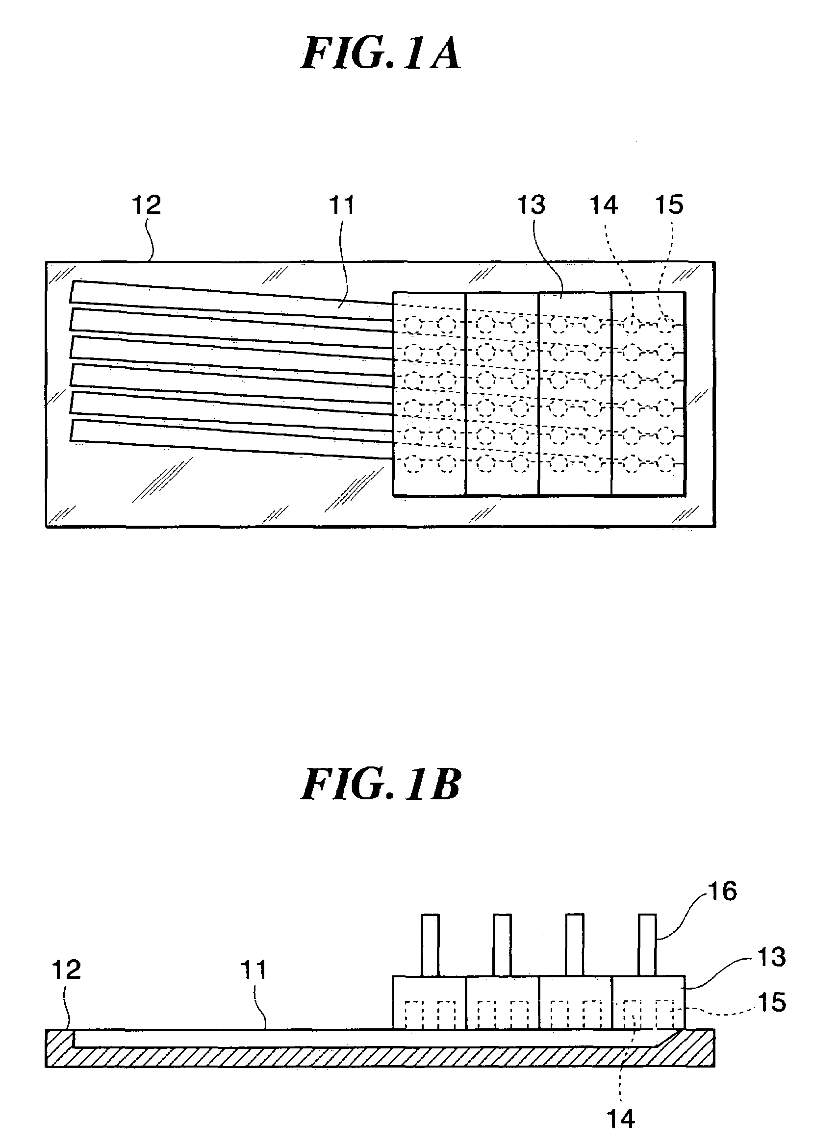
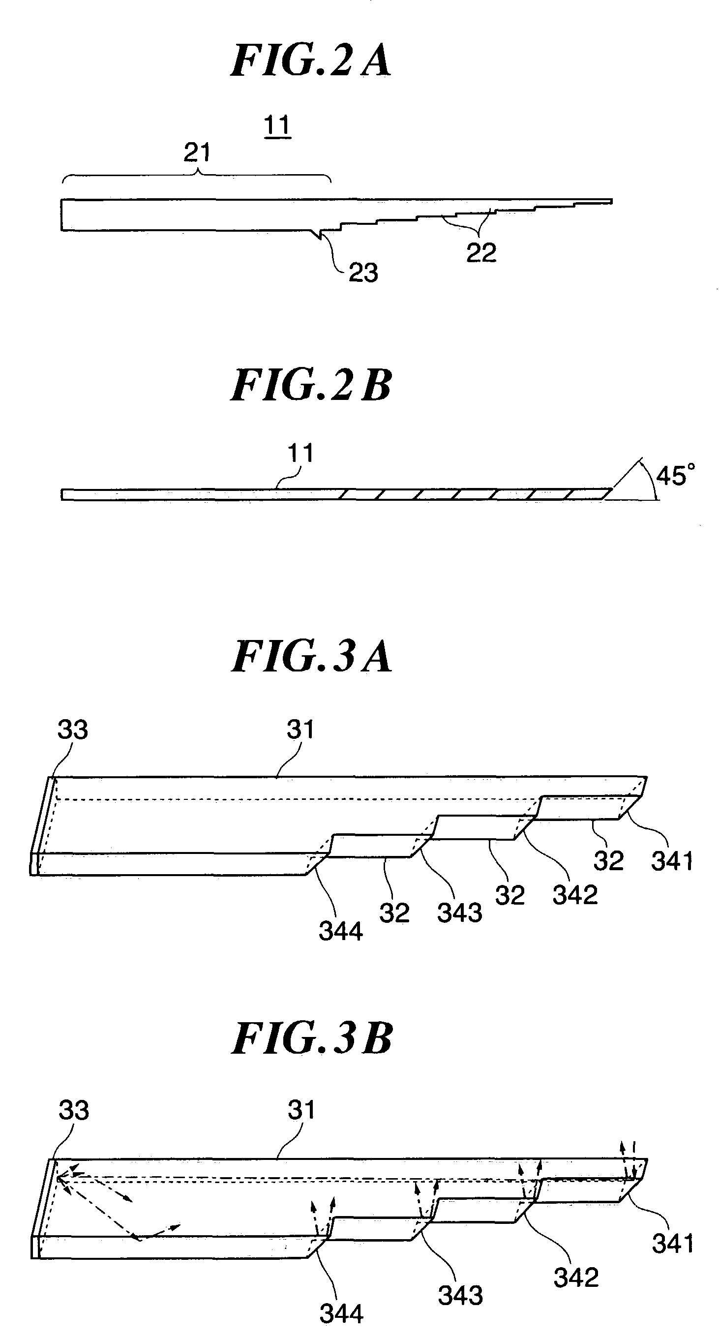
[0026]FIGS. 1A and 1B show an optical transmission device, which is a preferred embodiment of the present invention; FIG. 1A is a plan and FIG. 1B is a sectional view. In this embodiment, light guides 11 for six bits are fixed to a substrate 12 as illustrated. Each of the light guides 11 has stepped portions on each of which a light incidence / emission section is formed. The positioning of the light guides 11 relative to the substrate 12 can be accomplished by embedding the light guides in concaves formed in the substrate or, as will be described afterwards, by use of a triangular positioning projection provided on each light guide. The substrate 12 has an opening as illustrated, and plural optical connectors 13 are inserted into that opening. On each of the optical connectors 13 are arranged light receiving elements 14 and the light emitting elements 15, and each of the light receiving / emitting elements 14 and 15 is connected to an electronic circuit arranged on a board 16. In this ...


PUM


Abstract

An optical transmission device improved in optical coupling loss between light guides and optical elements and excelling in efficiency of light utilization is provided with light guides having light incidence / emission sections on plural stepped portions, a substrate that fixes the light guides, and light receiving elements and light emitting elements arranged on the substrate to match the light incidence / emission sections of the light guides. The light receiving elements and the light emitting elements are arranged on the substrate by use of optical connectors. Coefficients of linear expansion and the rates of dimensional variation due to water absorption (or alternatively due to water absorption rates) of the light guides and the substrate here are substantially equalized.

Description

BACKGROUND OF THE INVENTION[0001]1. Field of the Invention[0002]The present invention relates to an optical transmission device provided with light guides each having light incidence / emission sections and a substrate over which optical elements are arranged matching the light incidence / emission sections.[0003]2. Description of the Prior Art[0004]Known techniques in this regard include ones by which, when fixing light guides to a substrate, optical components are fabricated with the light guides and the substrate being matched in the coefficient of linear expansion. For instance, the Japanese Published Unexamined Patent Application No. 2001-4850 discloses a technique by which the coefficient of linear expansion of the substrate is matched to the material of optical waveguide. The yield of component production and the reliability of produced components are expected to be enhanced by the use of such a technique.[0005]There are various available methods for fixing the light guides and t...

Claims


Application Information

Patent Timeline
IPC IPC(8): G02B6/26G02B6/10G02B6/28G02B6/42
CPCG02B6/10G02B6/2817G02B6/4246G02B6/4249G02B6/4214
Inventor OKADA, JUNJINIITSU, TAKEHIROHAMADA, TSUTOMUYAMADA, HIDENORIOIKAWA, HIROSHI
Owner FUJIFILM BUSINESS INNOVATION CORP
Learn More