Variable gain amplifier device

a gain amplifier and variable gain technology, applied in the direction of gain control, volume compression/expansion having semiconductor devices, multiplex communication, etc., can solve the problems of difficult to realize the wide transmission power control range, the cdma system cannot perform correct communication,

Inactive Publication Date: 2006-06-20
KK TOSHIBA
View PDF30 Cites 24 Cited by
  • Summary
  • Abstract
  • Description
  • Claims
  • Application Information

AI Technical Summary

Benefits of technology

[0016]Therefore, it is an object of the present invention to provide a variable gain amplifier device configured of a MOS type transistor, capable of realizing exponential gain control with respect to a gain control signal.
[0018]According to a second aspect of the present invention, there is provided a variable gain amplifier device controlled by a first gain control signal, comprising: a gain controlled amplifier having a gain and including a first differential pair of first and second MOS type transistors configured to operate in a weak inversion region, and a second differential pair of seventh and eighth MOS type transistors configured to operate in a weak inversion region; and a control signal converter configured to convert the first gain control signal into a second gain control signal, and supply the second gain control signal to the gain controlled amplifier to exponentially vary the gain with respect to the first gain control signal.

Problems solved by technology

The CDMA system cannot perform correct communication if there is a large dispersion in the power of the transmission data from a plurality of users carried by a carrier of the identical frequency received by a base station.
This is because it is difficult to realize the wide transmission power control range only by the RF section since the variable gain range in the RF section is limited by the isolation between input and output.

Method used


Image

  • Variable gain amplifier device
  • Variable gain amplifier device
  • Variable gain amplifier device

Examples


first embodiment

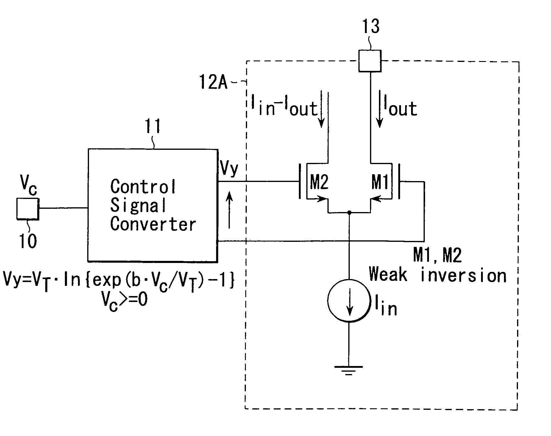
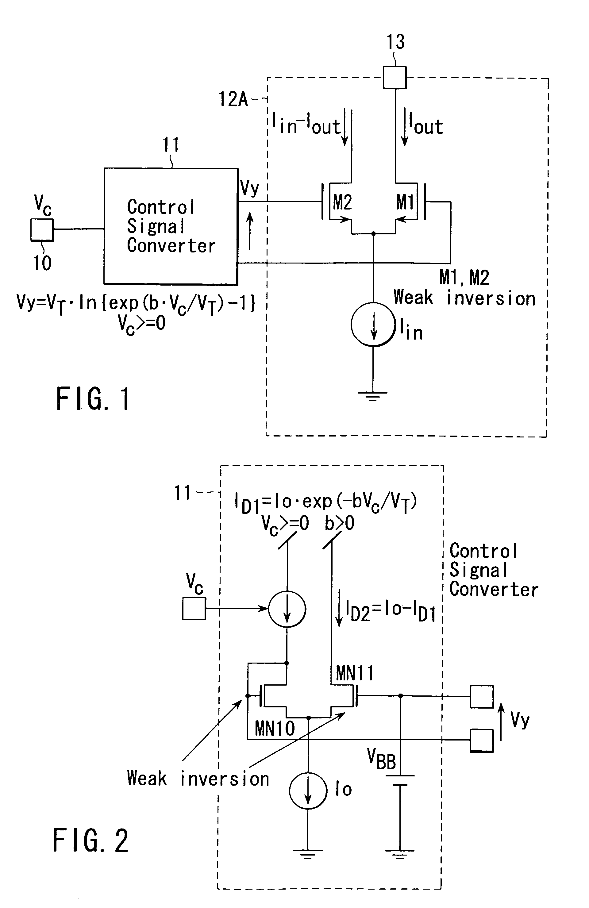
[0026]FIG. 1 shows a basic constitution of a variable gain amplifier device according to a first embodiment of the present invention. The variable gain amplifier device of this embodiment is configured by using a MOS type transistor. A first gain control signal Vc for externally controlling a gain of the variable gain amplifier device is input to a gain control signal input terminal 10. The first gain control signal Vc is converted, by a control signal converter 11, into a second gain control signal Vy for controlling a gain of a gain controlled amplifier 12A exponentially with respect to Vc. The second gain control signal Vy is supplied to the gain controlled amplifier 12A.

[0027]In the gain controlled amplifier 12A, a differential pair of N type MOS type transistors MN1, MN2 are provided. An input signal current Iin to be amplified is injected into a common source terminal of the transistors MN1, MN2, and an amplified output signal current Iout is introduced from a drain terminal o...

second embodiment

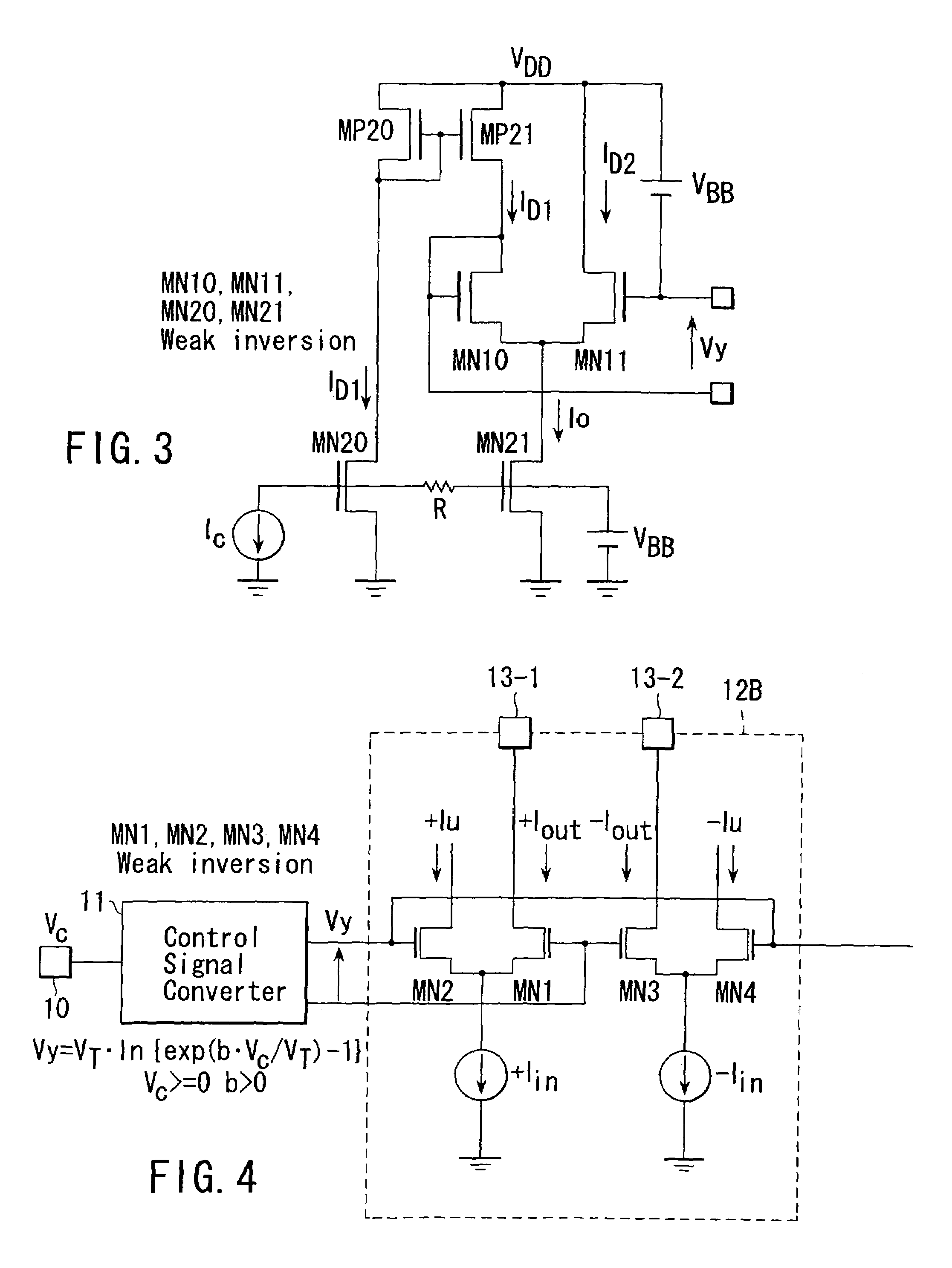
[0048]FIG. 4 shows the basic configuration in a case where the gain controlled amplifier is made to the differential configuration, as a variable gain amplifier device according to a second embodiment of the present invention. The first gain control signal Vc is converted by the control signal converter 11 into the second gain control signal Vy, and the second gain control signal Vy is input to a gain controlled amplifier 12B.

[0049]The gain controlled amplifier 12B includes a first differential pair of N type MOS type transistors MN1, MN2, and a second differential pair of N type MOS type transistors MN3, MN4. All of transistors MN1 to MN4 are set to operate in the weak inversion region.

[0050]The second gain control signal Vy from the control signal converter 11 is input between a gate terminal of the transistor MN2 and a gate terminal of the transistor MN1, and between a gate terminal of the transistor MN4 and a gate terminal of the transistor MN3. A first input signal current +Iin...


PUM


Abstract

A variable gain amplifier device controlled by a first gain control signal comprises a gain controlled amplifier having a gain and including a differential pair of first and second MOS type transistors configured to operate in a weak inversion region; and a control signal converter configured to convert the first gain control signal into a second gain control signal, and supply the second gain control signal to the gain controlled amplifier to exponentially vary the gain with respect to the first gain control signal.

Description

CROSS-REFERENCE TO RELATED APPLICATIONS[0001]This application is a divisional of U.S. application Ser. No. 09 / 950,630, filed Sep. 13, 2001, and is based upon and claims the benefit of priority from the prior Japanese Patent Application No. 2000-297453, filed Sep. 28, 2000, the entire contents of each of which are incorporated herein by reference.BACKGROUND OF THE INVENTION[0002]1. Field of the Invention[0003]The present invention relates to a variable gain amplifier device configured to vary a gain exponentially with respect to a gain control signal, applicable to a wireless communication apparatus such as a portable wireless device.[0004]2. Description of the Related Art[0005]Portable wireless devices such as a portable telephone are required to be reduced in size and weight so that they can be carried by a man, or mounted on a car or the like for use. Therefore, parts constitute the devices have been strongly desired to be monolithic ICs (integrated circuit) suitable to reductions...

Claims


Application Information

Patent Timeline
Patent Type & Authority Patents(United States)
IPC IPC(8): H04B7/00H03F3/45H03G3/02H03G1/00H03G3/00H03G3/10H03G7/06H04J13/00H04L27/00
CPCH03F3/45183H03G7/06H03G1/0029H03F2203/45246H03G3/00
Inventor OTAKA, SHOJIYAMAJI, TAKAFUMI
Owner KK TOSHIBA
Why Eureka
Try Eureka