Check patentability & draft patents in minutes with Patsnap Eureka AI!

Tool monitoring system and method

Inactive Publication Date: 2006-06-20
HONDA MOTOR CO LTD
View PDF15 Cites 31 Cited by
  • Summary
  • Abstract
  • Description
  • Claims
  • Application Information

AI Technical Summary

Problems solved by technology

It has thus proven difficult to quantify the amount of time needed to perform such operations.
It has further been observed that undefined work intervals invite low performance on the part of workers, which can also have a detrimental effect of productivity efficiency.
In some instances, the process durations were very short, making it difficult to obtain accurate timings.
Also, manual time measurement can be a subjective approach prone to human error.
However, there has not been a suitable method and apparatus for quantifying the time spent in these types of operations, or for comparing the time with the quality of the end-product.

Method used


Image

  • Tool monitoring system and method
  • Tool monitoring system and method
  • Tool monitoring system and method

Examples


Embodiment Construction

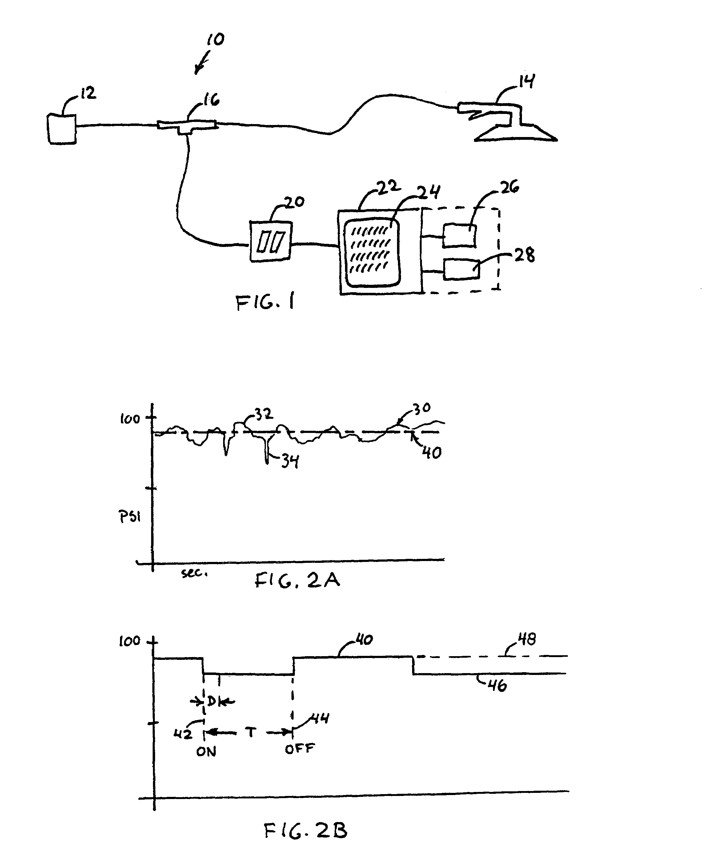
[0009]FIG. 1 shows a monitoring system 10 for measuring operational time of a powered tool. A power supply 12 is used to supply power to a powered tool 14. In the preferred embodiment, the power supply can be a compressed air supply supplied from a central air compressor through a plant pneumatic air supply system. The powered tool 14 is preferably a pneumatic tool powered by the compressed air supply, e.g. an air-powered buffer or grinder. However, it should be appreciated that embodiments could be contemplated in which other type power sources are used, such as electrical, hydraulic or any other suitable power supply as would occur to those skilled in the art.

[0010]A transducer 20 is provided, preferably an air pressure transducer in accordance with the preferred embodiment. The transducer 20 is in communication with the power supply 12, and is used for detecting power consumption (e.g. air pressure drops) associated with the respective powered and non-powered operational states. ...


PUM


Abstract

A transducer is provided in communication with a power supply of a powered tool for detecting power consumption associated with powered and non-powered operational states and generating a power consumption signal. A measuring implementation is provided for receiving the power consumption signal and measuring intervals associated with at least one of the powered and non-powered operational states, so as to produce an operational history of the powered tool corresponding to a predetermined time period. A production counter is used for counting production units produced by the powered tool during the predetermined time period. A correlating implementation is provided for correlating the operational history with the production units, so to as generate a productivity indicator.

Description

BACKGROUND OF THE INVENTION[0001]The presently disclosed embodiments are directed to the field of manufacturing performance monitoring and assurance. In a manufacturing process, productivity is directly impacted by the amount of time spent on a particular operation. In an assembly line environment the majority of operational time is clearly defined. Work that needs to be completed has little variation from product to product, such as stations for sanding and polishing defects in paint.[0002]At such stations, operational time is undetermined, since each job is uniquely performed on a “case by case” basis. It has thus proven difficult to quantify the amount of time needed to perform such operations. It has further been observed that undefined work intervals invite low performance on the part of workers, which can also have a detrimental effect of productivity efficiency.[0003]In order to improve efficiency, it has been contemplated to perform time studies to determine suitable lengths...

Claims


Application Information

Patent Timeline
IPC IPC(8): G01R15/00
CPCG01R21/133B25F5/00
Inventor BUTKA, STEPHEN J.NADERER, JAMES P.VANDERWEELE, RYAN A.
Owner HONDA MOTOR CO LTD
Features
  • R&D
  • Intellectual Property
  • Life Sciences
  • Materials
  • Tech Scout
  • Unparalleled Data Quality
  • Higher Quality Content
  • 60% Fewer Hallucinations
Learn More