Bistable hinge with dampening mechanism

a dampening mechanism and hinge technology, applied in the field of hinge assembly, can solve the problem of slow cam follower travel

Active Publication Date: 2006-06-27
SOUTHCO
View PDF51 Cites 46 Cited by
  • Summary
  • Abstract
  • Description
  • Claims
  • Application Information

AI Technical Summary

Benefits of technology

[0007]Briefly stated, a hinge according to one aspect of the present invention includes a first hinge part for connection to one of a hinged member and device housing and a second hinge part adapted for connection to the other of the hinged member and the device housing. The first hinge part has an axis and a cam follower while the second hinge part has a cam surface. An axial load bearing connector extends through axial bores of the first and second hinge parts. The cam follower is urged against the cam surface under bia

Problems solved by technology

The viscoelastic fluid dampens the spring force that urges the cam follower against the cam surface, thereby resulting in slower

Method used


Image

  • Bistable hinge with dampening mechanism
  • Bistable hinge with dampening mechanism
  • Bistable hinge with dampening mechanism

Examples


second embodiment

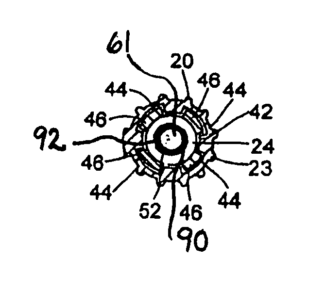
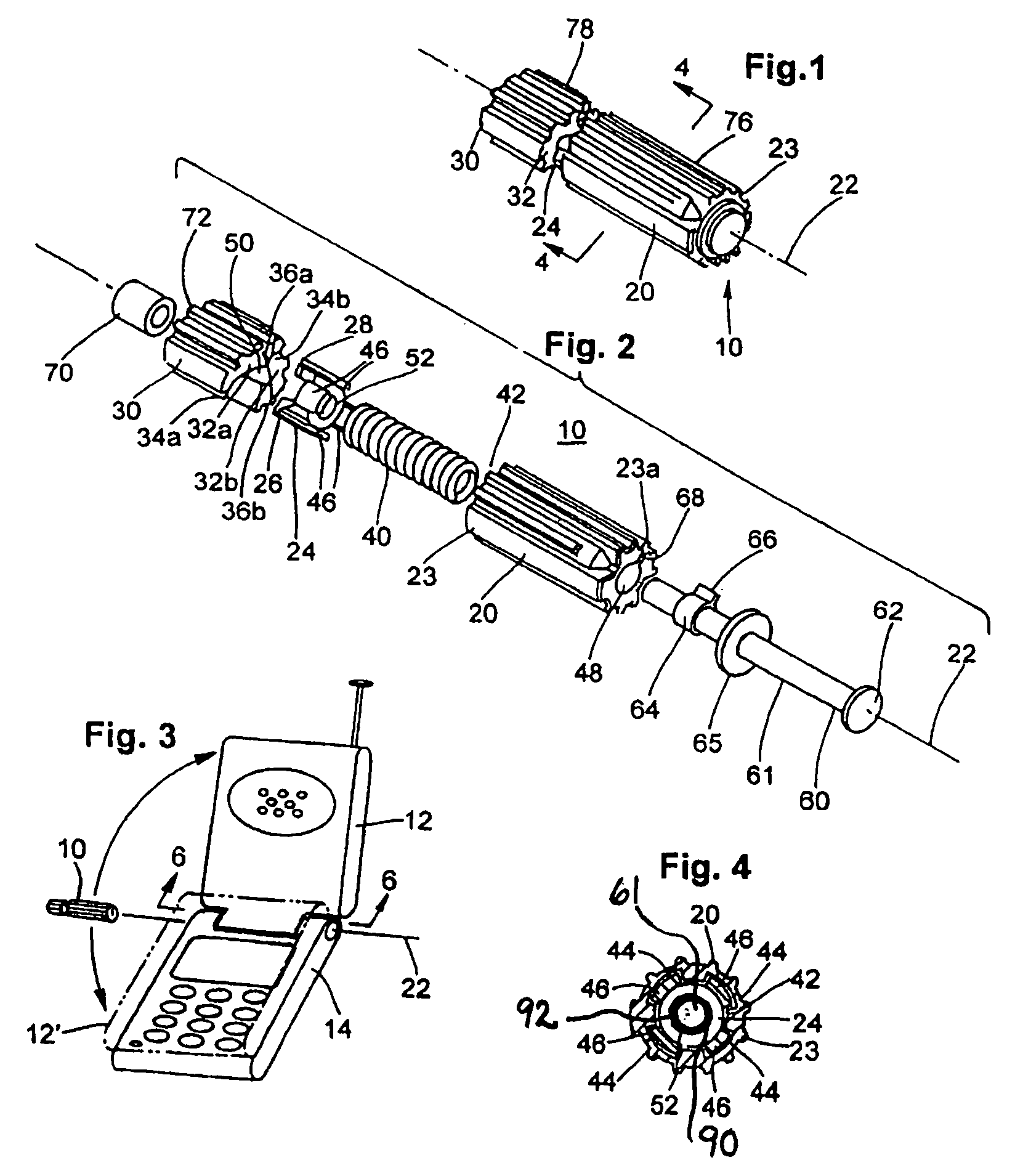
[0030]As shown in FIGS. 1 and 2, the hinge 10 includes a first hinge part 20 having a longitudinal axis 22 and a cam follower 24. The first hinge part 20 is adapted to be connected to one of the hinged member 12 and the device housing 14, and is preferably adapted to be connected to the hinged member 12. Preferably, the first hinge part 20 includes a separate housing 23 in which the cam follower 24 is movably located, as explained in detail below. However, it will be recognized by those skilled in the art from the present disclosure that the first hinge part 20 can be formed as a unitary piece with the cam follower 24, as will be explained in connection with the invention described in detail below.

[0031]The hinge 10 also includes a second hinge part 30 which is aligned with and rotatable about the axis 22 of the first hinge part 20. The second hinge part 30 includes a cam surface 32 on an end surface thereof. The cam follower 24 of the first hinge part 20 contacts the cam surface 32...

first embodiment

[0047]The first and second hinge parts 120, 130 include a projection 176, 178, which allow the first and second hinge parts 120, 130 to be connected to a hinged member and a device housing (not shown). One of the hinged member and the device housing in which the hinge 110 is to be used includes a slot (not shown) so that one of the projections 176, 178 can be axially displaced during hinge movement. Alternatively, an outer housing (similar to the housing 23 of the first embodiment) can be provided which includes an axial channel in which one of the projections 176 or 178 can slide. The outside of such housing would be anchored in one of the hinged member and the device housing (not shown) in order to prevent wear.

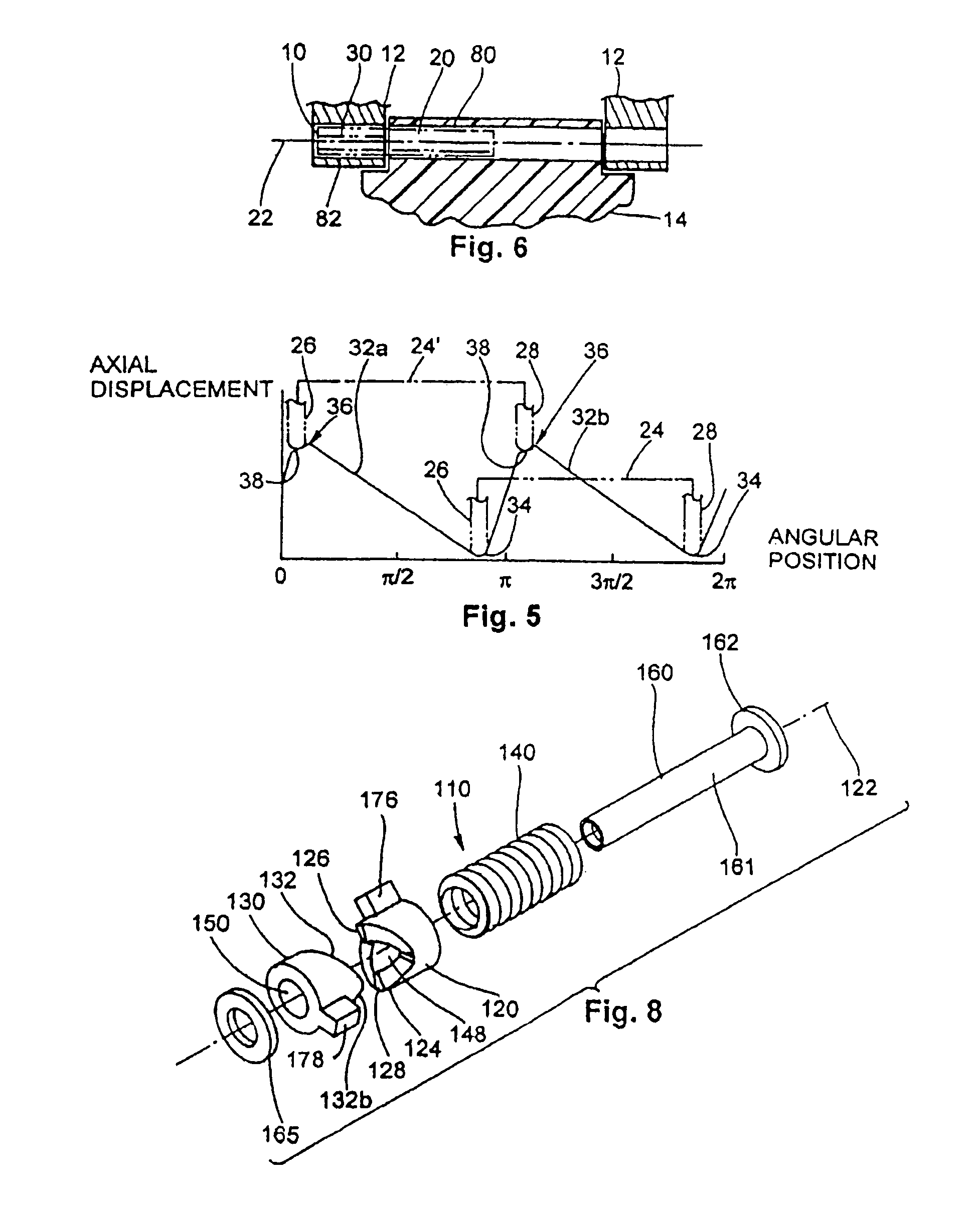
[0048]Referring to FIG. 9, a graph showing the change in axial displacement of the cam surfaces 132a, 132b based on angular position about the axis 122 is provided. In a first position 134, the contacts 126, 128 of the cam follower 124 are located at a lowermost position th...

fourth embodiment

[0059]With reference now to FIG. 15, a cross section of a hinge device 510 in accordance with a sixth preferred embodiment of the invention is illustrated. The elements of the hinge 510 are similar to the elements of the hinge 410 in accordance with the fourth embodiment, as described above, and like elements have been identified with like reference numerals with the prefix “5” in place of the prefix “4”. Accordingly, a detailed description of these similar elements has been omitted for the sake of brevity.

[0060]The hinge device 510 is somewhat similar in construction to the hinge device 410 and includes a second hinge part 530 with a housing 580 and a cam follower 582 that is movably located within the housing 580. The cam follower 530 is preferably similar in shape to the second hinge part 430 previously described, but may alternatively be shaped as in the FIG. 4 embodiment. In this alternative embodiment, the inside surface of the housing 580 would be complementary in shape. An o...


PUM


Abstract

A hinge for controlling a pivotal rate of movement. The hinge includes a first hinge part and a second hinge part that is pivotally mounted to the first hinge part. The first hinge part movable to and between open and closed positions relative to the second hinge part. A connector extends along an axis and the first and second hinge parts are pivotally mounted around the connector on the axis. A gap is defined between at least one of the first and second hinge parts and the connector. A damping fluid is located within the gap for controlling a relative rate of movement of the first and second hinge parts between the open and closed positions.

Description

CROSS-REFERENCE TO RELATED APPLICATIONS[0001]This application claims the benefit of U.S. Provisional Patent Application Nos. 60 / 477,073, filed Jun. 9, 2003 and 60 / 496,827, filed Aug. 21, 2003, each entitled, “Bistable Hinge with Dampening Mechanism”.BACKGROUND OF THE INVENTION[0002]The present invention relates to a hinge assembly for rotatably coupling a hinged member to a device housing, and more particularly, to a position holding, viscoelastic dampened, self-latching hinge for holding a hinged member in one of an open position and a closed position relative to a device housing.[0003]In certain hinge applications, it is desirable to provide a hinge which can maintain a hinged member in an open position or a closed position and dampen movement of the hinged member between the open and closed positions at a relatively slow and constant rate. One such application is in the highly competitive field of portable communication devices, (e.g., cellular and PCS phones or light weight cove...

Claims


Application Information

Patent Timeline
IPC IPC(8): E05F1/08E05DE05D11/08E05D11/10E05F3/20H04M1/02
CPCH04M1/0216G06F1/1679G06F1/1681E05D11/084Y10T16/5387E05F3/20E05Y2201/21E05Y2201/254E05Y2201/266E05Y2900/606Y10T16/540255Y10T16/54028Y10T16/304Y10T16/540256E05D11/1078
Inventor LOWRY, DAVID A.
Owner SOUTHCO
Why Eureka
Try Eureka