In particular, as far as diesel engines are concerned, the main problems are caused by the presence in the exhaust gases of nitric oxides (
NOx) and particulate, whereas carbon monoxides (CO) and hydrocarbons (HC) do not cause particular problems.
As the accumulation of particulate on the inner surfaces of the walls of the channels increases, there is also an increase in the pressure drop on the particulate filter and therefore in the counter-pressure generated by the particulate filter itself.
The particulate thus cannot be accumulated indefinitely, since high levels of accumulation give rise to:deterioration of the performance, drivability and consumption of the engine, until at the limit the engine itself stalls; anddestruction of the particulate filter in the event of self-priming and uncontrolled
combustion of the particulate; in fact, in the presence of large accumulations of particulate, in particular driving conditions there can be triggering of “critical” regeneration phenomena, consisting of sudden and uncontrolled
combustion of the particulate: consequently, the high temperatures which are generated inside the
ceramic matrix of the particulate filter can give rise to damage to the latter.
The regeneration of a particulate filter constitutes the main problem associated with the use of this type of filter in the automobile field.
In particular, the methods for self-priming of the combustion of the particulate based on the use of an additive require:an exhaust
system comprising a catalyser and a particulate filter integrated in a single casing (canister);a particulate filter with a very high volume, typically equivalent to approximately twice the
engine displacement;an additive in the
diesel fuel (based on
cerium), which makes it possible to reduce the regeneration self-priming temperature by 100–150° C.;a very
complex system for adding and automatic metering of the additive
on board the vehicle; andengine control strategies in order to increase the temperature at the particulate filter intake, since the thermal levels necessary cannot be reached in
normal conditions of use of the engine; in fact, this type of
system operates correctly only when the engine is running with medium loads, whereas in the event of prolonged functioning with low loads (for example when driving in towns) and / or in the presence of low external temperatures (in winter), in many cases the temperature of the exhaust gases cannot reach that of self-priming.
Although the methods for self-priming of the combustion of the particulate which are based on the use of an additive permit self-priming of the regeneration of the particulate filter at about 450–500° C., and the particulate filter generates low counter-pressure, they have the following significant disadvantages, which do not allow their benefits to be used adequately and fully:complexity, in particular for the
system for adding and automatic metering of the additive;need for installation of a particulate filter with a high volume, since the additive which is present in the
diesel fuel leaves a deposit of ash inside the particulate filter itself which increases progressively;need to “re-clean” ash from the particulate filter approximately every 80,000 km, despite the large volume of the particulate filter itself; in fact the
cerium produces a large quantity of ash which accumulates inside the filter, together with the particulate, and cannot be eliminated by means of the regeneration; this therefore gives rise to a progressive increase in the counter-pressure of the filter on the engine, as the distance travelled by the vehicle increases, and to the consequent need to carry out periodically dismantling and cleaning of the filter in order to eliminate the ash which has accumulated; andhigh costs, both for the system for adding and automatic metering of the additive and for the particulate filter with a large volume.
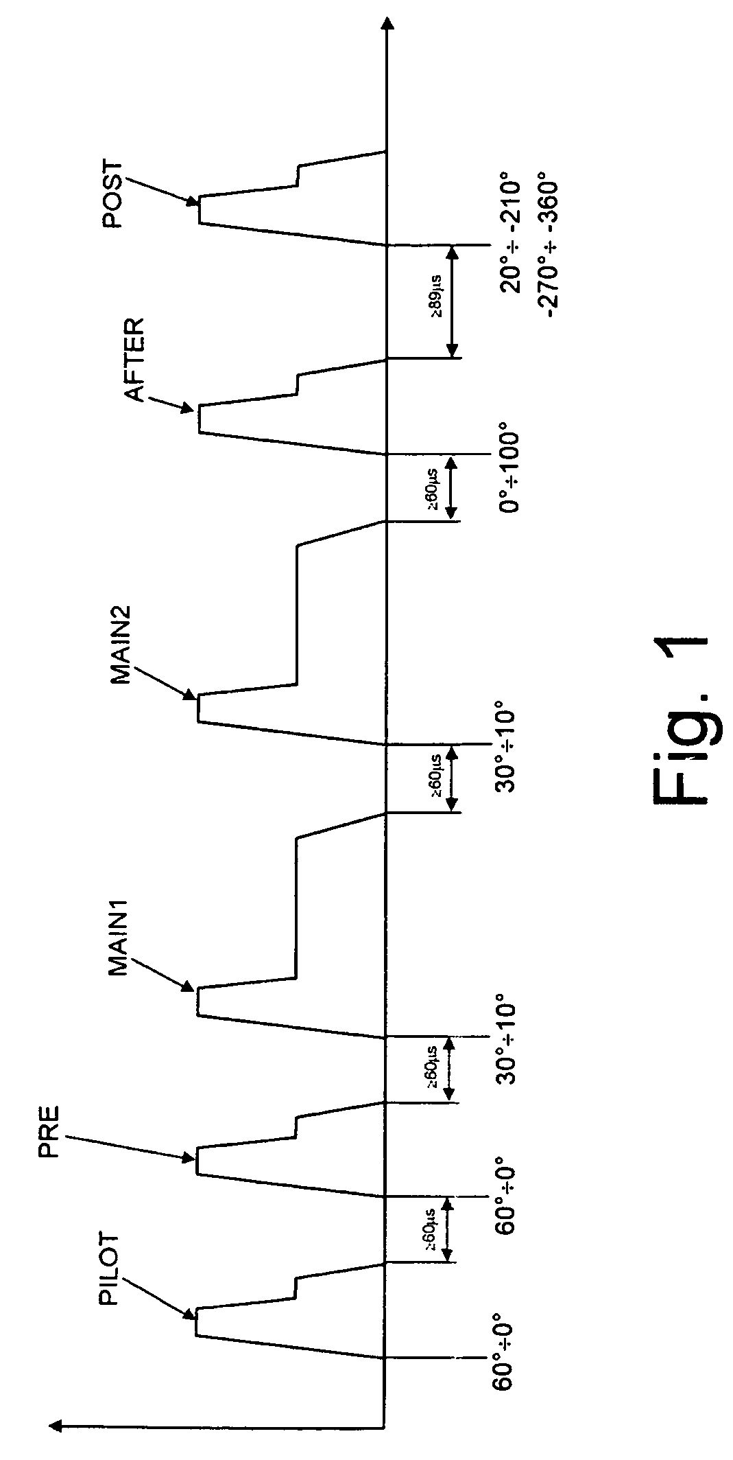
In detail, the strategy which is based on the
delay of the main injection has limits caused by the fact that the main injection cannot be delayed beyond a certain limit, otherwise it would give rise to unstable combustion which would cause misfiring, with consequent production of white / blue fumes and problems of drivability, and in particular to phenomena of “failure”.
For these reasons, this strategy does not make it possible to obtain high temperatures at the intake of the particulate filter, in particular at low engine speeds and with low loads.
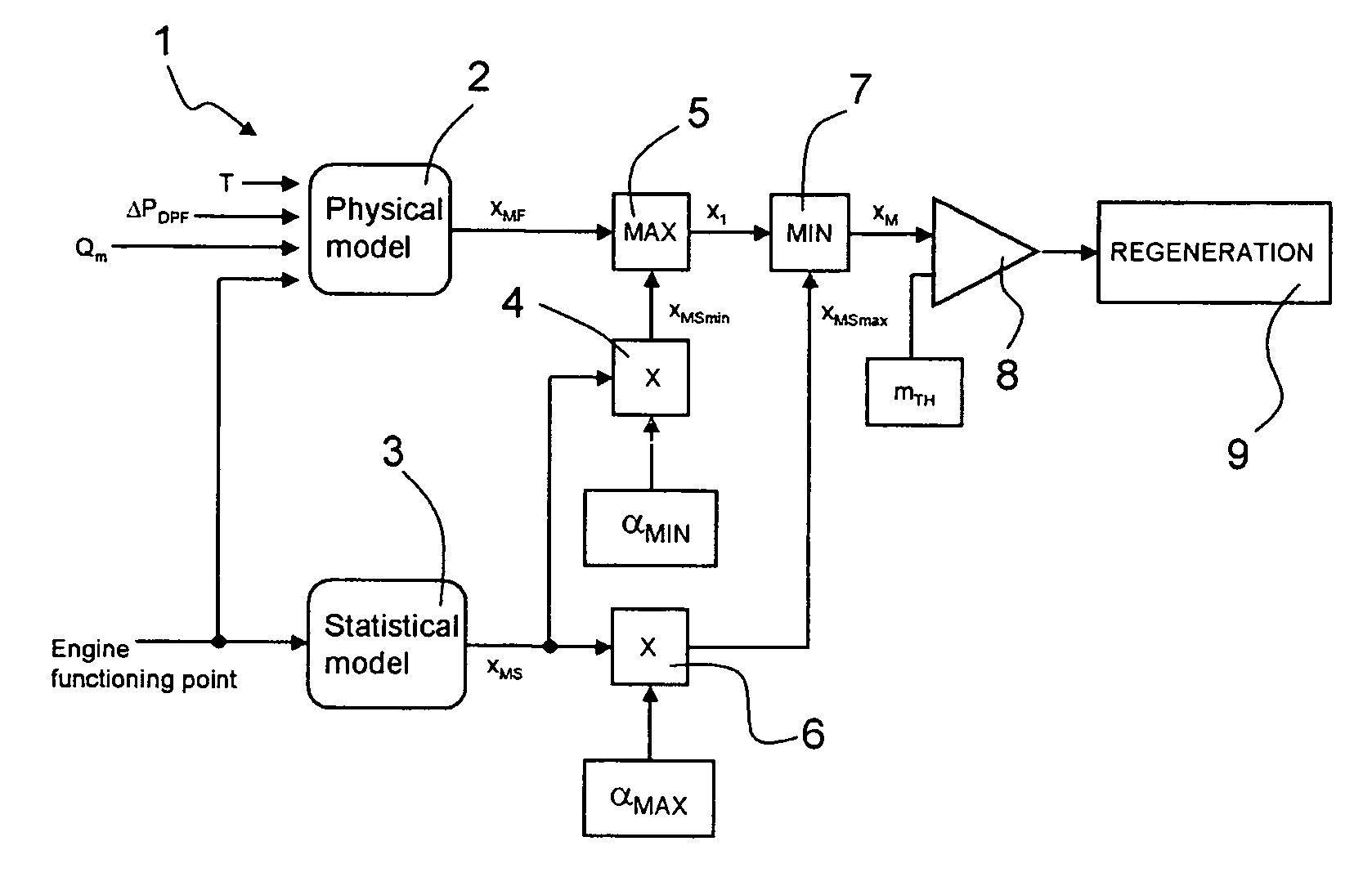
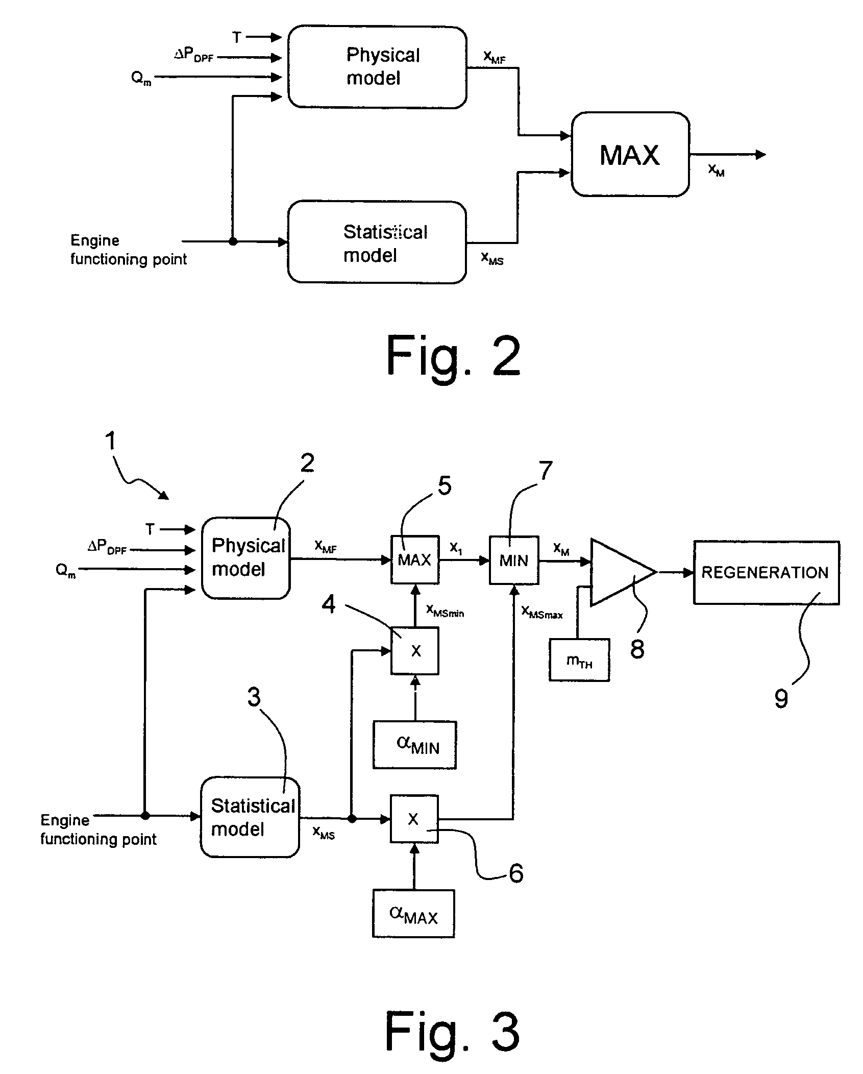
In addition, account must also be taken of any abnormalities of functioning of the engine, which can involve a significant increase in the emissions of particulate and the accumulation of quantities of particulate such as to detract seriously from the reliability of the particulate filter.
In fact, the accumulation of particulate inside the particulate filter is a strongly non-
linear process which is dependent on time, but is also strongly affected by the point of work of the engine.
However, this solution is not satisfactory.
In addition, in certain situations, these sensors may be affected by errors which cannot be detected by suitable control systems, and are caused by electrical malfunctioning (slow drifts, variations of offset and
gain) or mechanical malfunctioning (
dirt, obstructions, etc.); in this case, the estimate of the accumulated particulate is not correct, and if it is overestimated, it may give rise to activation of the regeneration stage before this is actually necessary.
In addition, as indicated, the regeneration strategy involves the use of the
POST injection, which, however, involves a delicate problem associated with the
dilution of the lubricating oil.
In fact, at the engine angles which are used for this injection, inside the cylinder there is
low resistance to the jet of fuel, which consequently comes into contact with the film of oil present on the walls of the cylinder, thus causing
dilution of the film.
The increase in the frequency of regeneration caused by the overestimate made by the
physical model can thus lead to excessive
dilution of the engine oil, with consequent deterioration of the quality of the
lubricant.
The liquid
lubricant may thus no longer be able to carry out its main functions (reduction of friction, protection against wear of the mechanical units,
discharge of heat, etc.), with consequent possible damage to the engine.

