Molding die for optical element with lens-barrel

Inactive Publication Date: 2006-06-27
FUJI PHOTO OPTICAL CO LTD
View PDF11 Cites 5 Cited by
  • Summary
  • Abstract
  • Description
  • Claims
  • Application Information

AI Technical Summary

Benefits of technology

[0012]Therefore, the invention has an object to provide a molding die for an optical element with a lens-barrel, allowing a less optical-axis deviation and a constant axial position of the optical element molded on the inner peripheral surface of the lens-barrel in manufacturing the optical element with a lens-barrel.

Problems solved by technology

Particularly in the case of manufacturing a small optical element with a lens-barrel, because the wall of the lens-barrel 10 is thin in thickness, a problem has arisen in terms of the strength of the lens-barrel 10.

Method used


Image

  • Molding die for optical element with lens-barrel
  • Molding die for optical element with lens-barrel
  • Molding die for optical element with lens-barrel

Examples


first embodiment

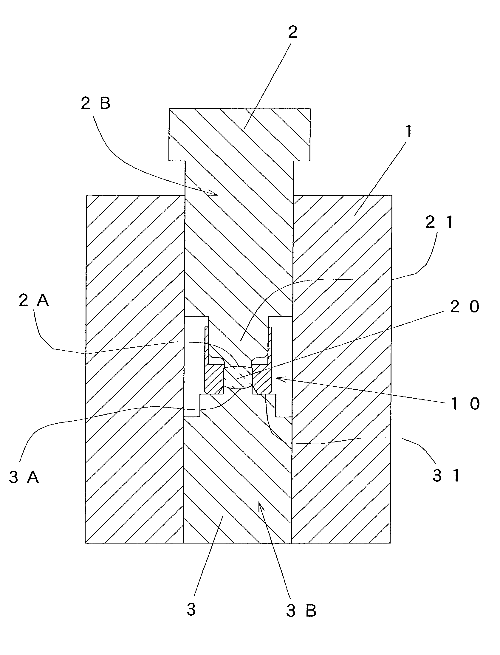
[0021]FIG. 3 shows a cross sectional view of a molding die for an optical element with a lens-barrel according to the invention. Therein, the figure shows a molding die for forming an optical element with a lens-barrel, in which an optical element is tightly joined to the inner peripheral surface of the upper end side of a lens barrel 10 set in the molding die comprising a guide die 1, a upper die 2 and a lower die 3.

[0022]The molding die comprises the tubular guide die 1, the upper die 2 and lower die 3 molded like a circular cylinder, and an optical raw material (or a glass material) 20 is sandwiched, heated and pressurized between the upper die 2 and lower die 3 sliding in the tubular guide die 1, thereby transferring transfer surfaces 2A and 3A to the optical raw material 20 to mold an optically functioning surface. At the same time, the optical raw material 20 is caused to flow in the outer periphery thereof, and the outer edge of the raw material 20 is caused to tightly join t...

second embodiment

[0039]FIG. 6 shows a cross sectional view of a molding die for an optical element with a lens-barrel according to the invention. The figure shows a molding die for forming an optical element with a lens-barrel, in which the optical element is tightly joined to the inner peripheral surface on the lower end side of the lens-barrel 10, which is set in the molding die comprising the guide die 1, upper die 2, and lower die 3.

[0040]In the same manner as the first embodiment, the present embodiment also comprises the tubular guide die 1, the upper die 2 and lower die 3 molded like a circular cylinder. Here, the optical raw material (or glass raw material) 20 placed in the lens-barrel 10 is sandwiched, heated and pressurized between the upper die 2 and lower die 3 sliding in the tubular guide die 1. Thereby, the transfer surfaces 2A and 3A are transferred to the optical raw material 20 to mold an optically functioning surface thereon, and at the same time, the optical raw material is caused...


PUM

PropertyMeasurementUnit
Diameteraaaaaaaaaa

Abstract

A molding die for an optical element with a lens-barrel in which the lens-barrel is set in the molding die includes a tubular guide die, a upper die and a lower die sliding in the guide die Also an optical raw material is placed in the lens-barrel and the optical element is sandwiched, heated and pressurized between the upper die having a transfer surface and the lower die having a transfer surface, thereby integrally forming the optical element in the lens-barrel. Outside diameter portions designed to be equal to the inner diameter of the guide die are provided for the upper die and lower die, wherein the outside diameter portion is fitted in the guide die so as to be able to slide only in the axial direction.

Description

BACKGROUND OF THE INVENTION[0001]1. Field of the Invention[0002]The invention relates to a molding die for forming an optical element with a lens-barrel, in which an optical raw material (or glass raw material) is placed in the lens-barrel set in the molding die and heated and pressurized between a upper die and a lower die and thereby the optical element is integrally formed in the lens-barrel.[0003]2. Description of the Related Art[0004]In recent years, in forming an optical element (or a glass-formed component) by heat softening an optical raw-material (or an optical glass) in a heating furnace and thereafter heating and pressurized it between a upper die and a lower die, a method of manufacturing an optical element with a lens-barrel has been used. In this method, a lens-barrel is set in a molding die comprising a guide die, the upper die and the lower die, and also an optical raw material (or a glass raw material) is placed in the lens-barrel, and the optical raw material is sa...

Claims


Application Information

Patent Timeline
IPC IPC(8): C03B11/00C03B11/08B28B3/08G02B7/02G02B3/00
CPCC03B11/08C03B2215/50C03B2215/79C03B2215/72C03B2215/60
Inventor YAMANAKA, HAJIME
Owner FUJI PHOTO OPTICAL CO LTD
Why Eureka
Try Eureka