Apparatuses and methods for balancing combustion air and exhaust gas for use with a direct-vent heater appliance

a technology of combustion air and exhaust gas, which is applied in the direction of gaseous heating fuel, stoves or ranges, ways, etc., can solve the problems of time-consuming and laborious process of balancing, not particularly efficient heaters for burning fireplaces, and frequent cleaning

Inactive Publication Date: 2006-06-27
TRAVIS IND
View PDF37 Cites 32 Cited by
  • Summary
  • Abstract
  • Description
  • Claims
  • Application Information

AI Technical Summary

Benefits of technology

[0009]One method for balancing combustion air and exhaust gas in a direct-vent heater appliance in accordance with an embodiment of the invention includes igniting a fire in the firebox, providing a flow of combustion air to the firebox and a flow of exhaust gas from the firebox, visually analyzing the flame to determine if the flows of combustion air and exhaust gas should be adjusted to modify the flame, and manipulating an actuator shaft that synchronously

Problems solved by technology

Traditional wood-burning fireplaces are not particularly efficient heaters, they tend to be dirty and require frequent cleaning due to the nature of the fuel used, and they require a constant supply of wood or other fuel.
Limited ac

Method used


Image

  • Apparatuses and methods for balancing combustion air and exhaust gas for use with a direct-vent heater appliance
  • Apparatuses and methods for balancing combustion air and exhaust gas for use with a direct-vent heater appliance
  • Apparatuses and methods for balancing combustion air and exhaust gas for use with a direct-vent heater appliance

Examples


Embodiment Construction

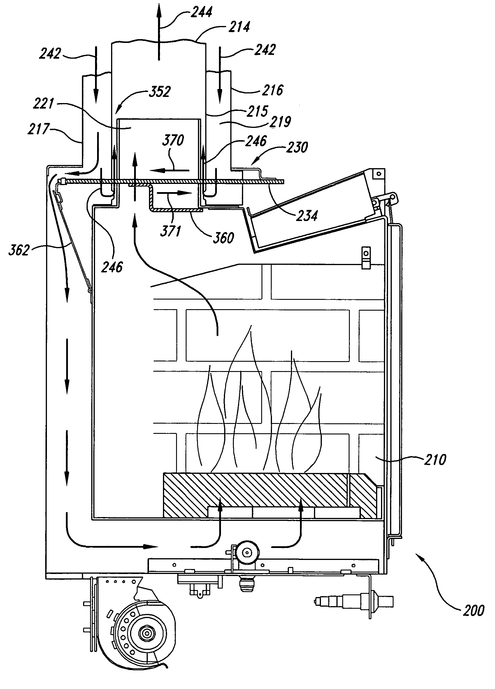
[0016]In the following description, certain specific details are set forth in order to provide a thorough understanding of various embodiments of the invention. The present disclosure describes apparatuses and methods for controlling the flow of combustion air and exhaust gas in a direct-vent heater appliance. Many specific details of certain embodiments of the invention are set forth in the following, description and in FIGS. 2 through 5 to provide a thorough understanding of these embodiments. One skilled in the art will understand, however, that the present invention may have additional embodiments, or that the invention may be practiced without several of the details described below. In other instances, well known structures associated with direct-vent heater appliances, such as gas lines and burner assemblies in a firebox, have not been shown or described in detail to avoid unnecessarily obscuring the description of the embodiments of the invention.

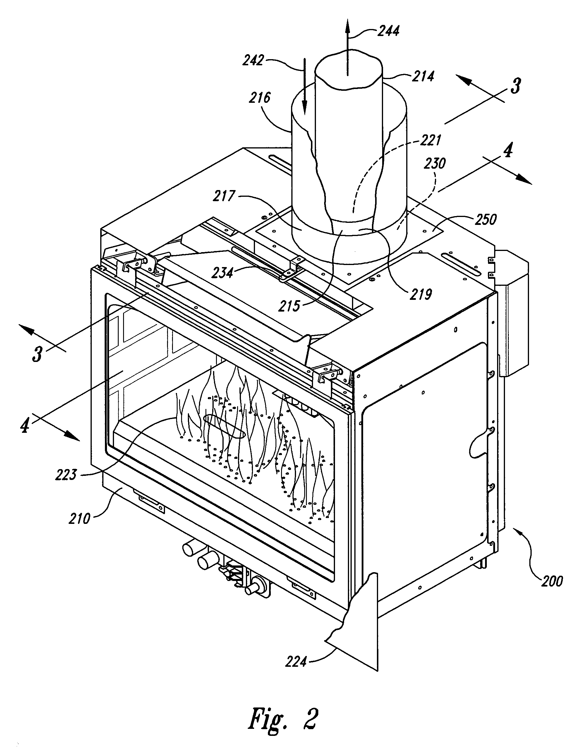
[0017]FIG. 2 is a partial cut...


PUM


Abstract

A combustion air and exhaust gas balancing system for use with a direct-vent heater appliance. The balancing system includes a combustion air valve in fluid communication with a combustion air duct and an exhaust gas valve in fluid communication with an exhaust gas duct. The combustion air valve is operatively coupled to the exhaust gas valve with an actuator. The combustion air and exhaust gas valves are shaped and sized so that a single operation of the actuator simultaneously adjusts the flow of combustion air into the firebox and the flow of exhaust gas out of the firebox and provide selected flame characteristics in the firebox. In one aspect of this embodiment, a movement of the actuator in a first direction simultaneously increases the flow of combustion air and exhaust gas, and a movement of the actuator shaft in a second direction simultaneously restricts the flow of combustion air and exhaust gas. The actuator shaft is securable after final adjustment of the combustion air and exhaust gas flows to maintain the selected adjustment. In another embodiment, the exhaust gas duct includes a dilution air inlet aperture that permits combustion air to pass from the combustion air duct into the exhaust gas duct without first passing through the firebox.

Description

CROSS-REFERENCE TO RELATED APPLICATION[0001]This application is a continuation of U.S. patent application Ser. No. 09 / 703,206 filed Oct. 31, 2000, now abandoned which is hereby incorporated by reference.TECHNICAL FIELD[0002]This invention is directed to direct-vent heater appliances, and more particularly, to apparatuses and methods for balancing combustion air and exhaust gas in direct-vent heater appliances.BACKGROUND OF THE INVENTION[0003]Vented heater appliances are well known and commonly used in residential dwellings and other structures for heating and esthetic purposes. Examples include gas-burning furnaces and gas-burning and wood-burning fireplaces. Traditional wood-burning fireplaces are not particularly efficient heaters, they tend to be dirty and require frequent cleaning due to the nature of the fuel used, and they require a constant supply of wood or other fuel. In view of the disadvantages of traditional wood-burning fireplaces, there has been a move to cleaner and m...

Claims


Application Information

Patent Timeline
IPC IPC(8): F24B1/19F24B1/187
CPCF24B1/1808F24C15/002F24C3/122F24B5/028
Inventor ATEMBOSKI, ALANKING, LESLIE E.
Owner TRAVIS IND
Why Eureka
Try Eureka