Fuel injector

a technology of fuel injector and cylinder head, which is applied in the direction of fuel injector pump, operating means/releasing devices of valves, machines/engines, etc., can solve the problems of coupler breakage, unsatisfactory long-term sealing by rubber sleeves, and loss of function, etc., to achieve high viscosity and convenient manufacture

Inactive Publication Date: 2006-06-27
ROBERT BOSCH GMBH
View PDF13 Cites 21 Cited by
  • Summary
  • Abstract
  • Description
  • Claims
  • Application Information

AI Technical Summary

Benefits of technology

[0018]Advantageous in this embodiment is that it allows a convenient manufacture. The coupler is to be filled with a highly viscous hydraulic fluid. At the same time, it is advantageous if the actuator chamber is fill

Problems solved by technology

The sealing by a rubber sleeve, which is pressed against the end section of the guide cylinder and the slave piston by two clamping rings, is unsatisfactory in the long term.
The highly viscous hydraulic fluid and the fuel thus may mix over time, and the coupler break down.
When gasoline,

Method used


Image

  • Fuel injector
  • Fuel injector
  • Fuel injector

Examples


Embodiment Construction

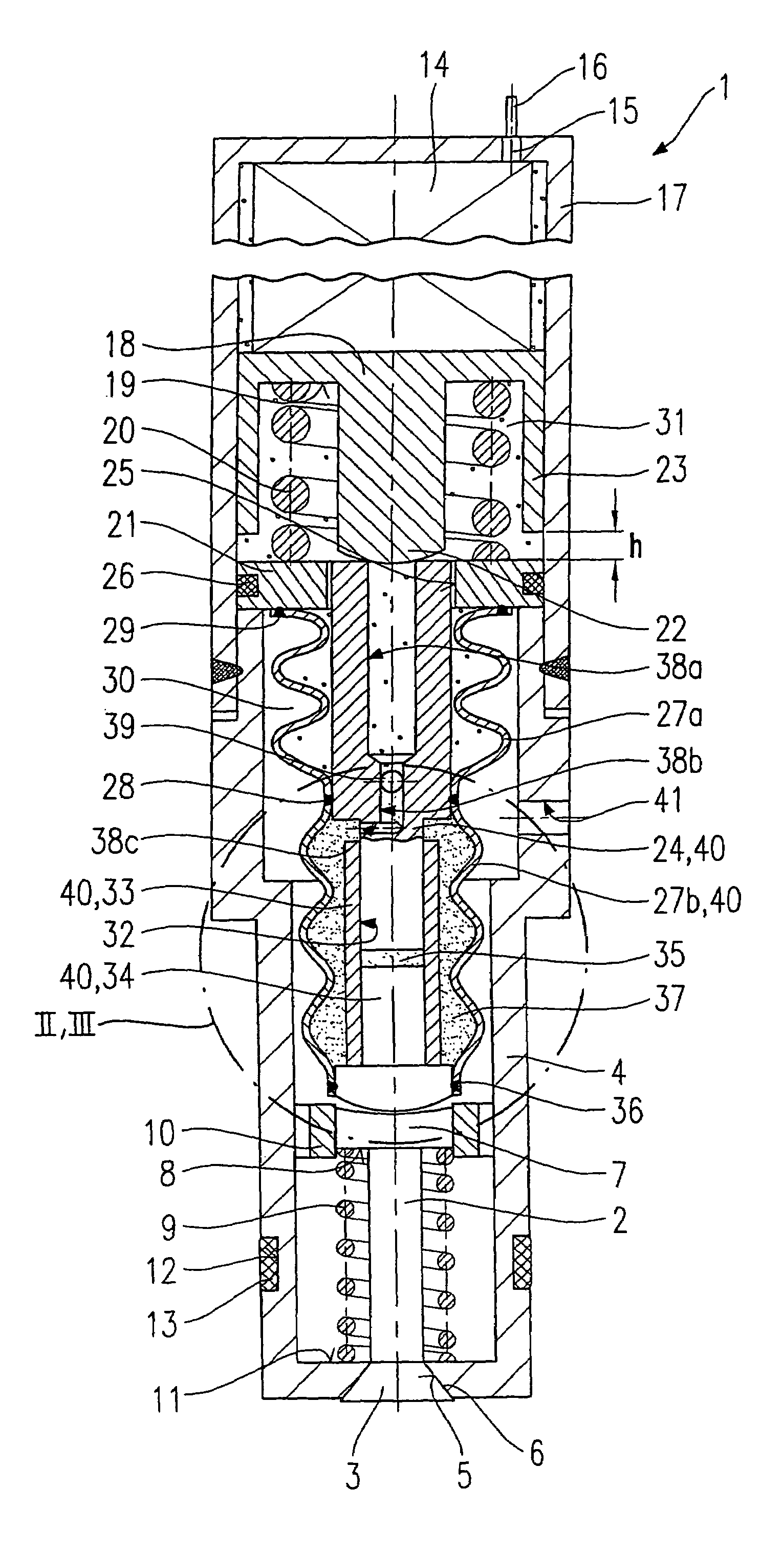
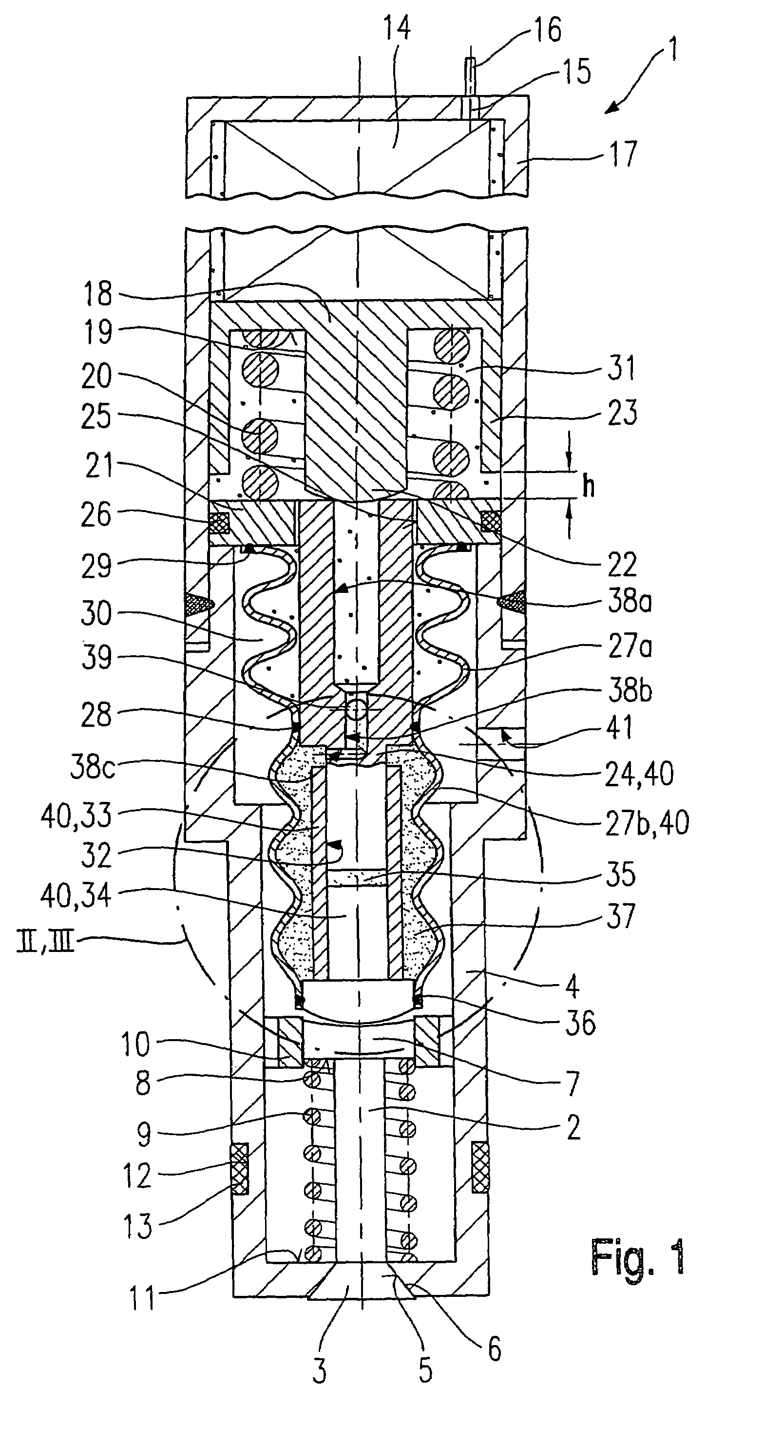
[0023]Fuel injector 1, schematically shown in FIG. 1, has a valve needle 2, which is joined to a valve-closure member 3 and cooperates via this valve-closure member 3 with a valve-seat surface 5 formed in a valve member 4 to form a valve-sealing seat. Fuel injector 1 is an outwardly opening fuel injector, which is provided with a valve needle 2 that opens toward the outside. Valve needle 2 is guided in a valve-needle guide 10 by a guide section 7, which includes a spring system 8 for a valve-closure spring 9. Valve-closure spring 9 is braced against a second spring system 11 at valve body 4 and prestresses valve needle 2 with a force that presses valve-closure member 3 against valve-seat surface 5. A sealing ring 13 positioned in a groove 12 seals the ring gap (not shown here) between valve body 4 and a bore (likewise not shown) in a cylinder head of an internal combustion engine.

[0024]To actuate valve needle 2, a piezoelectric or magnetostrictive actuator 14, to which a voltage may...


PUM


Abstract

A fuel injector for fuel-injection systems of internal combustion engines having a piezoelectric or magnetostrictive actuator, includes a hydraulic coupler which actuates a valve-closure member (3) formed on a valve needle. The valve-closure member cooperates with a valve-seat surface to form a valve-sealing seat. The coupler includes a master piston and a slave piston which are guided in bores of a guide sleeve. Located between the master piston and the slave piston is a pressure chamber filled with a hydraulic fluid. A corrugated tube is positioned around the guide sleeve which is sealingly joined to the master piston at one end and to the slave piston at the other end, and which seals a supply chamber for the hydraulic fluid from a surrounding fuel chamber.

Description

FIELD OF THE INVENTION[0001]The present invention relates to a fuel injector.BACKGROUND INFORMATION[0002]European Patent No. EP 0 477 400 describes a fuel injector having a path transformer for a piezoelectric actuator in which the actuator transmits a lifting force to a master piston. The master piston is in force-locking connection to a guide cylinder for a slave piston. The slave piston, the guide cylinder and the master piston sealing the guide cylinder form a hydraulic chamber. A spring, which presses the master piston and the slave piston apart, is situated in the hydraulic chamber. Surrounding an end section of the guide cylinder and the slave piston is a rubber sleeve by which a supply chamber for a viscous hydraulic fluid is sealed from a fuel chamber. The viscosity of the hydraulic fluid is adapted to the ring gap between the slave piston and the guide cylinder.[0003]The slave piston mechanically transmits a lifting movement to a valve needle, for example. When the actuato...

Claims


Application Information

Patent Timeline
IPC IPC(8): B05B1/08F02M59/00F16K31/00F02M51/00F02M51/06F02M61/08F02M61/16
CPCF02M51/0603F02M61/08F02M61/167F02M2200/707F02M2200/16F02M2200/703
Inventor HOHL, GUNTHER
Owner ROBERT BOSCH GMBH
Why Eureka
Try Eureka