Separating cyclone and method for separating a mixture

a technology of mixture and cyclone, which is applied in the direction of vortex flow apparatus, liquid degasification, separation process, etc., can solve the problems of limited separation efficiency, and achieve the effects of improving separation efficiency, improving separation efficiency, and increasing throughpu

Inactive Publication Date: 2006-06-27
FMC TECH CV
View PDF7 Cites 3 Cited by
  • Summary
  • Abstract
  • Description
  • Claims
  • Application Information

AI Technical Summary

Benefits of technology

[0005]It is an object of the present invention to being about a separation of the mixture where the above stated drawback is wholly or at least partially obviated. It is a further object of the invention to provide a separating cyclone with improved properties. This is understood to mean a cyclone with a higher separating efficiency at a given composition and pressure of the mixture for admitting and / or, at a given pressure drop, a higher throughput with a substantially constant separating efficiency. This can also be understood to mean that at a determined throughput the pressure drop over the cyclone is lower.
[0016]At the position of the distal part of the flow body, the tangential speed of the mixture increases because the angular momentum is sustained. Too low an axial speed can result in an uncontrollable separation of the flow on the inner surface of the outer casing. Too high an axial speed can prevent a so-called “vortex-breakdown”, which is necessary for the separating process. It has been found that when the distal part of the flow body has a conical form, a relatively high separating efficiency can be achieved.
[0018]Another preferred embodiment relates to an axial separating cyclone. In an axial separating cyclone the inlet means comprise an inlet part extending axially relative to the outer casing and debauching in the flow space. In such an axial cyclone it is possible to substantially reduce the pressure drop for a given flow rate.
[0022]The second outlet means preferably comprise a discharge channel extending through the flow body, the inlet opening of which channel is positioned at the distal end of the flow body. This provides an efficient discharge of the light fraction.

Problems solved by technology

The separating efficiency is however limited in that a part of the mixture flowing along the flow body and set into rotation detaches from the surface of the flow body.

Method used


Image

  • Separating cyclone and method for separating a mixture
  • Separating cyclone and method for separating a mixture
  • Separating cyclone and method for separating a mixture

Examples


Embodiment Construction

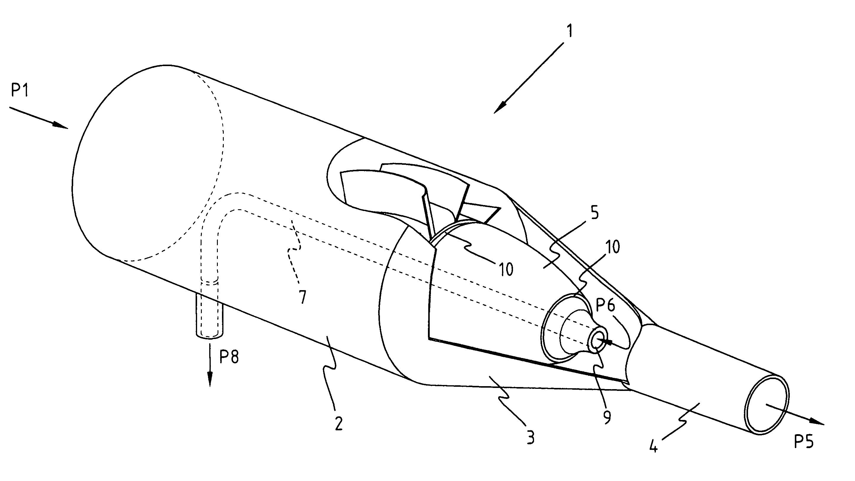
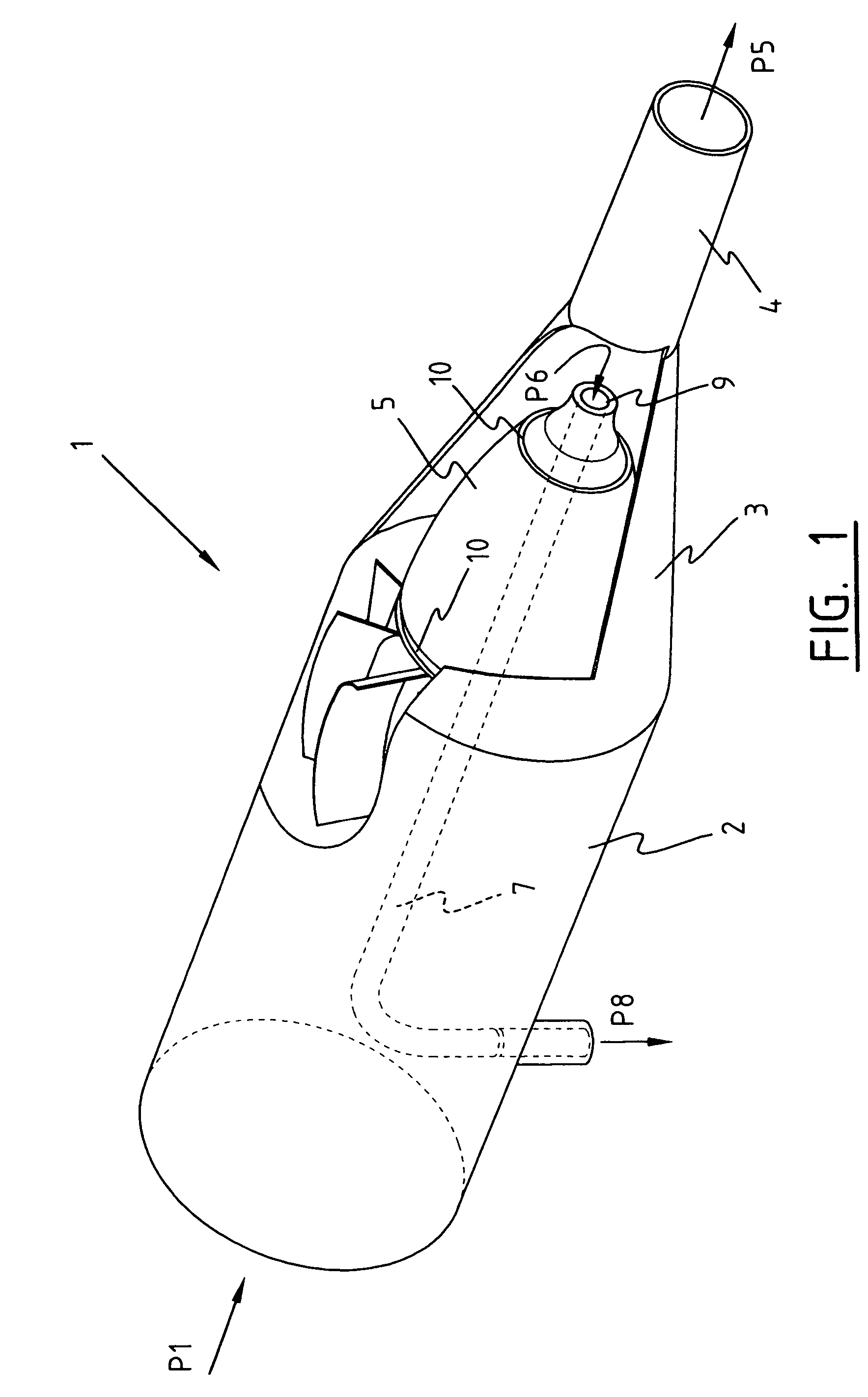
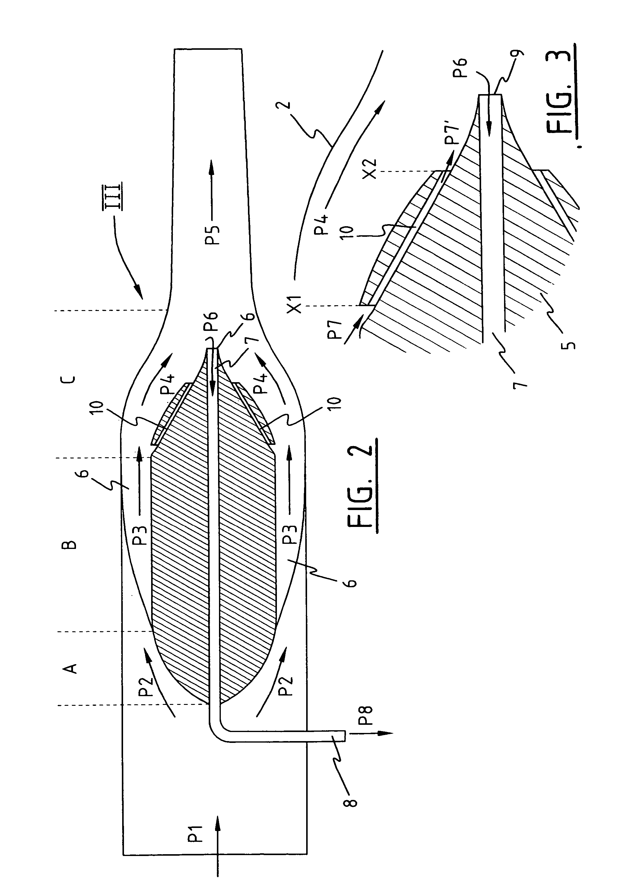
[0039]Referring to FIGS. 1–3, a first preferred embodiment of a cyclone separator is shown. A mixture is supplied of two or more liquids of different density. A relatively heavy liquid (also referred to hereinbelow as the heavy fraction), such as water, is mixed with a relatively light liquid, such as oil. It is however equally possible to separate a mixture of gases or a gas / liquid mixture.

[0040]Separating cyclone 1 has for its object to separate the supplied mixture into a part containing substantially the heavy liquid (also referred to hereinbelow as the heavy fraction), and a part containing substantially the light liquid (also referred to as the light fraction). Separating cyclone 1 is constructed from a cylindrical outer casing, inside which a flow space is defined. The outer casing comprises an initial pipe 2 which has a substantially constant diameter, a middle pipe 3, the diameter of which decreases in axial direction, and a cylindrical end pipe 4.

[0041]A flow body is arran...


PUM

PropertyMeasurementUnit
densityaaaaaaaaaa
diameteraaaaaaaaaa
centrifugal forcesaaaaaaaaaa

Abstract

A separating cyclone for at least partially separating a mixture of fluids of different density into a light fraction with a relatively low density and a heavy fraction with a relatively high density, comprising a flow body in a flow space between the flow body and casing around the flow body wherein at least one bypass channel is provided in the distal part of the flow body, via which channels a part of the mixture flowing along the flow body in the flow space can be guided. Also, a method for separating the above stated mixtures.

Description

BACKGROUND OF THE INVENTION[0001]The present invention relates to a separating cyclone for at least partially separating a mixture of fluids of different density into a light fraction with a relatively low density and a heavy fraction with a relatively high density. The invention also relates to a flow body for such a separating cyclone and to a method for at least partially separating said mixture.[0002]Known for the purpose of separating mixtures of mutually insoluble liquids, such as oil and water, are separating cyclones wherein use is made of the difference in density between water and oil to bring about the separation. The mixture for separating is set into rotation in a tube, whereby under the influence of the occurring centrifugal forces the relatively heavy water is flung against the wall of the tube and the relatively light oil moves to the centre of the tube. The oil and the water are hereby separated from each other spatially, which provides the option of discharging the...

Claims


Application Information

Patent Timeline
Patent Type & Authority Patents(United States)
IPC IPC(8): B01D45/12B01D17/02B04C5/06B04C5/103B04C5/12
CPCB01D17/0217B04C5/12B04C5/103B04C5/06
Inventor STANBRIDGE, DAVID
Owner FMC TECH CV
Why Eureka
Try Eureka