

Rotation control device of working machine
a technology of rotating control device and working machine, which is applied in the direction of motor/generator/converter stopper, dynamo-electric converter control, instruments, etc., can solve the problems of operating performance, braking and holding effect cannot be guaranteed, and the loss of energy is larg
- Summary
- Abstract
- Description
- Claims
- Application Information
AI Technical Summary
Benefits of technology
Problems solved by technology
Method used
Image

Examples
first embodiment (see figs.1 to 4)
First Embodiment (See FIGS. 1 to 4)
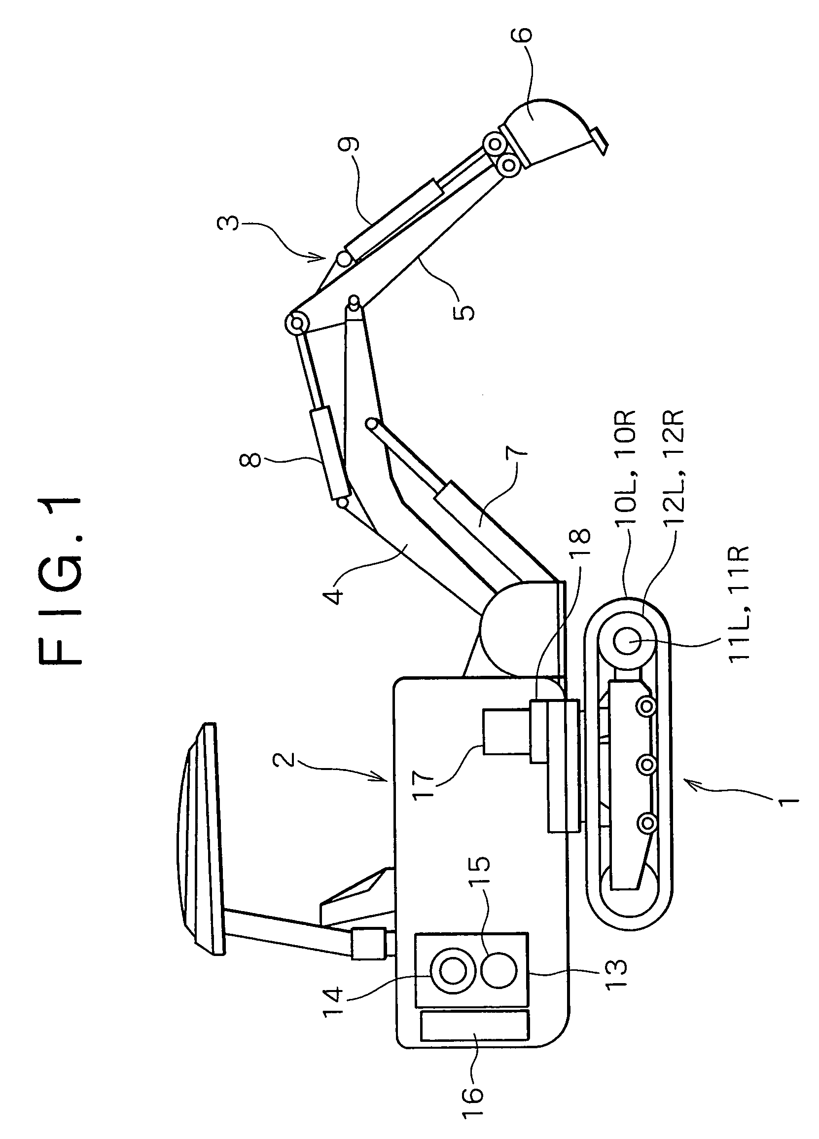
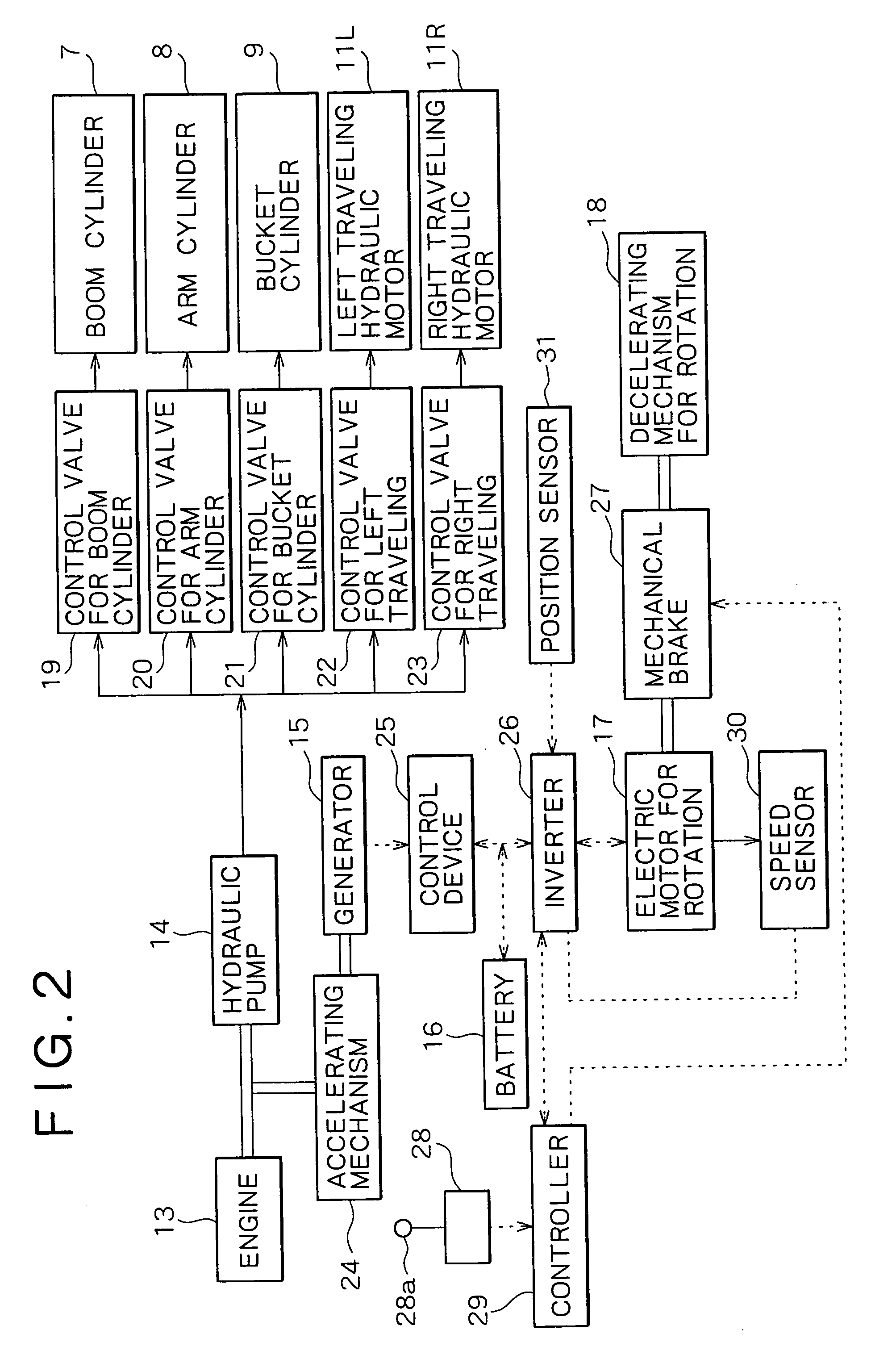
[0042]FIG. 1 illustrates the schematic configuration of an entire excavator and the arrangement of devices therein, and FIG. 2 the block configuration of a drive and control system.
[0043]As shown in FIG. 1, on a crawler type lower traveling body 1 is rotatably mounted on an upper traveling body 2, which is equipped with an excavating attachment 3. The excavating attachment 3 includes a boom 4, an arm 5, a bucket 6, a boom cylinder 7, an arm cylinder 8, and a bucket cylinder 9.
[0044]The lower traveling body 1 includes left and right crawlers 10L and 10R, which are rotatably driven and traveled by traveling motors 11L and 11R and reduction gears 12L and 12R, respectively.
[0045]On the upper rotating body 2 are mounted an engine 13, a hydraulic pump 14, a generator 15, the pump and generator being driven by this engine 13, a battery 16, an electric motor for rotation 17, and a decelerating mechanism for rotation 18.
[0046]As shown in FIG. 2, discharge o...
second embodiment (see figs.1 , 2 , and 5)
Second Embodiment (See FIGS. 1, 2, and 5)
[0073]In the first embodiment, speed control is carried out depending on the amount of lever operation outside the neutral range N, while, in the second embodiment, speed control with torque limitations is carried out outside the neutral range N.
[0074]The configuration of the second embodiment is apparently the same as that of the first embodiment. Note that these embodiments differ from each other only in the contents of control performed by the controller 29 and the inverter 26. Thus, FIGS. 1 and 2 are cited, and in addition thereto FIG. 5 is used to explain the detailed contents of the control.
[0075]In Accelerating Rotation
[0076]Within the neutral range N, control of the second embodiment is the same as that of the first embodiment. When the lever operation amount exceeds the simultaneous use zone C, the mechanical brake 27 is released thereby to perform the only position holding control, an effect of which holds the rotating body 2 on the...
third embodiment (see figs.6 to 11)
Third Embodiment (See FIGS. 6 to 11)
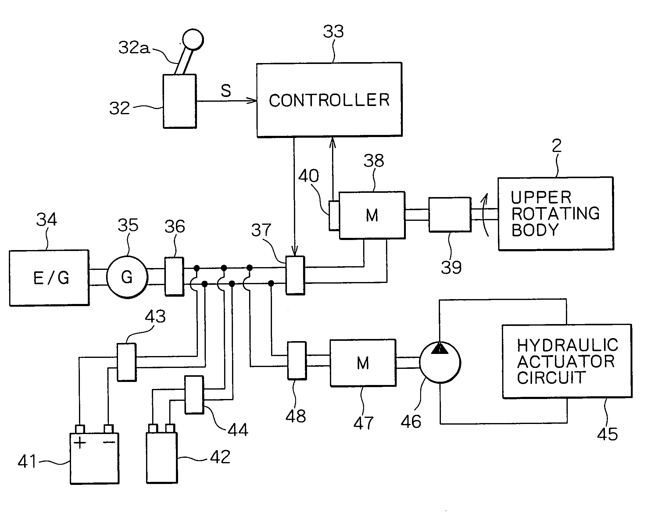
[0090]FIG. 6 illustrates the entire configuration of such a rotation control device according to the third embodiment.
[0091]In the figure, reference numeral 32 denotes a rotation operating portion (which is identical to the rotation operating portion 28 of FIG. 2, for example, potentiometer) serving as the rotation operating means. This rotation operating portion 32 is operated by a lever 32a. A command signal responsive to the amount of its operation is inputted into the controller 33 serving as the control means.
[0092]Reference numeral 34 denotes an engine, and reference numeral 35 a generator 35 driven by this engine 34. Power from this generator 35 is transmitted to a rotation electric motor 38 via an inverter for the generator 36 and an inverter for the electric motor 37. Rotational force of the rotation electric motor 38 is transmitted to the upper rotating body 2 via a reduction gear 39, causing the rotating body 2 to rotate around a rotati...
PUM
 Abstract
Description
Claims
Application Information