Apparatus and method for coding/decoding TFCI bits in an asynchronous CDMA communication system

a communication system and asynchronous technology, applied in the field of cdma mobile communication system, can solve the problems of increasing delay and inability to use hard split methods, and achieve the effect of simplifying calculations

Inactive Publication Date: 2006-06-27
SAMSUNG ELECTRONICS CO LTD
View PDF15 Cites 23 Cited by
  • Summary
  • Abstract
  • Description
  • Claims
  • Application Information

AI Technical Summary

Benefits of technology

[0020]It is still another object of the present invention to provide an apparatus and method for dividing a correlation calculating process by inverse fast Hadamard transform into several steps, and simplifying calculations performed in the respective steps.

Problems solved by technology

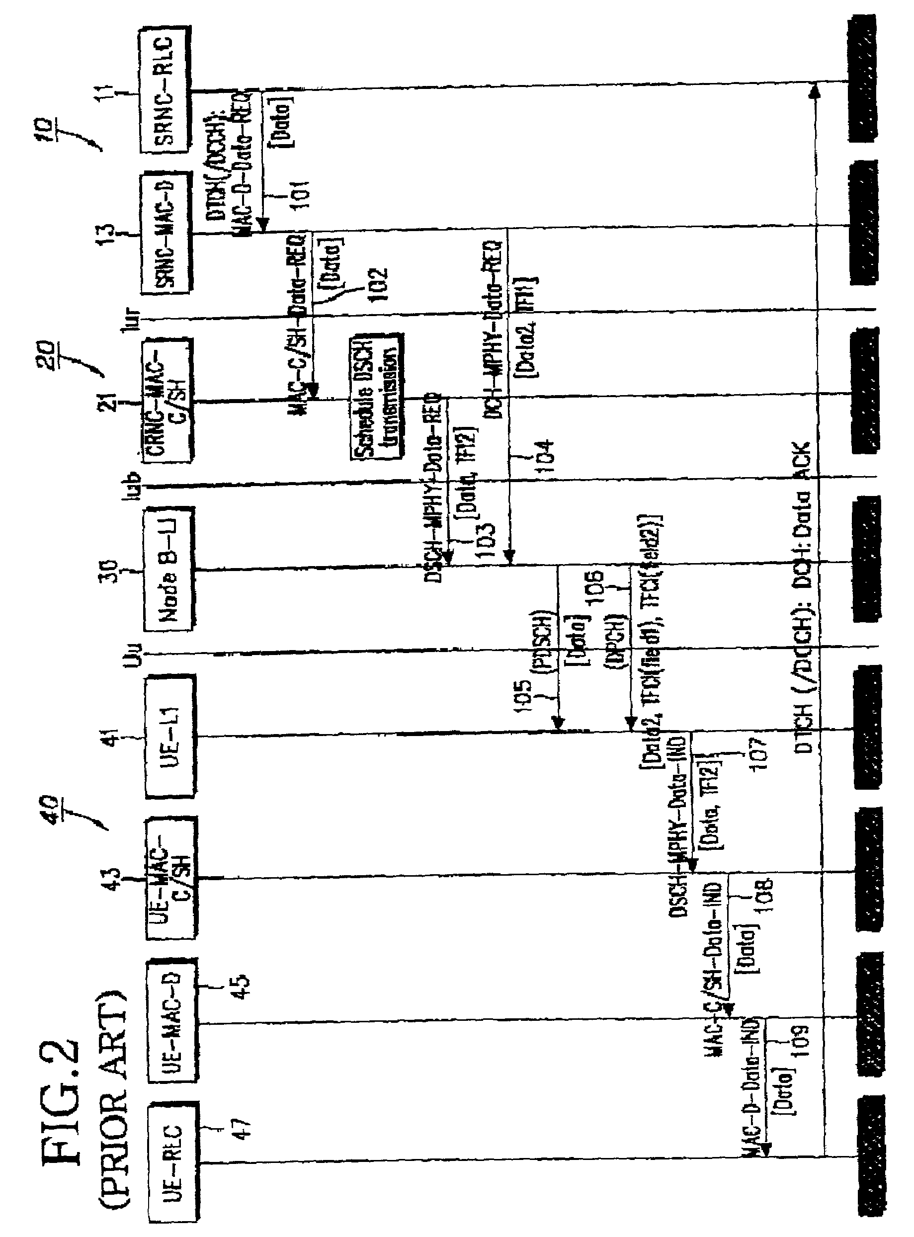
In addition, when the MAC-C / SH 305 is separated from the MAC-D 303 on the lur, i.e., when the MAC-C / SH 305 exists in the DRNC (Drift RNC) and the MAC-D 303 exists in the SRNC, the scheduling information and the TFCI information are exchanged on the lur, causing an increase in the delay.
Therefore, if there are more than 32 sorts of information for the DSCH or DCH, the hard split method cannot be used.

Method used


Image

  • Apparatus and method for coding/decoding TFCI bits in an asynchronous CDMA communication system
  • Apparatus and method for coding/decoding TFCI bits in an asynchronous CDMA communication system
  • Apparatus and method for coding/decoding TFCI bits in an asynchronous CDMA communication system

Examples


first embodiment (

Decoder)

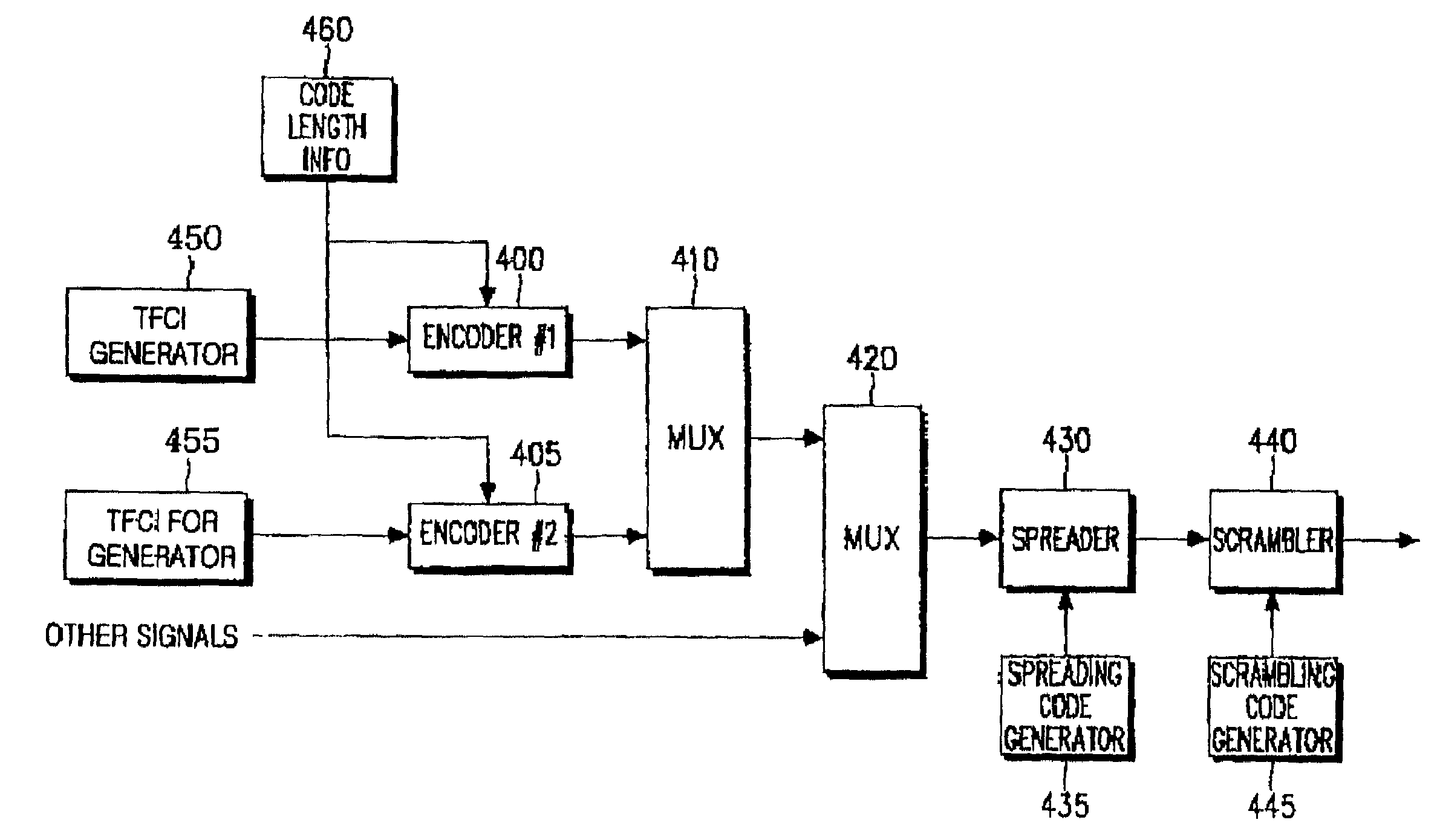
[0111]FIG. 7 illustrates a detailed structure of the decoders 600 and 605. Referring to FIG. 7, received symbols r(t) are provided to the zero inserter 700, and at the same time, code length information is provided to the controller 770. The controller 770 stores puncturing position information based on a code length of the received symbols, and provides the stored puncturing position information to the zero inserter 700. For example, the controller 770 provides the zero inserter 700 with information on 29 puncturing positions for a coding rate (3,1), information on 26 puncturing positions for a coding rate (6,2), information on 23 puncturing positions for a coding rate (9,3), information on 20puncturing positions for a coding rate (12,4), information on 14 puncturing positions for a coding rate (18,6), information on 11 puncturing positions for a coding rate (21,7), information on 8 puncturing positions for a coding rate (24,8), and information on 5 puncturing positions for...

second embodiment (

Decoder)

[0112]FIG. 14 illustrates a structure of the first and second decoders 600 and 605 of FIG. 6. Referring to FIG. 14, coded symbols r(t) received from the encoder are provided to a zero inserter 1400, and at the same time, information on a code length used by the encoder is provided to a controller 1430. The controller 1430 stores information on puncturing positions in association with the code lengths available for the encoder, and provides control information stored therein in association with the code length information to the zero inserter 1400. The code length information indicates the code length or the coding rate used in the encoder, while the control information indicates the puncturing positions. The puncturing positions represent the positions of the symbols pruned to obtain a desired coded symbol length corresponding to the bits received from the encoder. For example, Table 5 illustrates the puncturing positions stored in association with the code lengths.

[0113]

TAB...


PUM


Abstract

A method for decoding received data in a decoder which receives data from an encoder varying a length of a Walsh code according to a coding rate of transmission data, and has maximum IFHT (Inverse Fast Hadamard Transform) stages capable of decoding even the data encoded by a Walsh code with a maximum length. The method comprises selecting at least one IFHT stage among the maximum IFHT stages according to a length of the Walsh code used for the received data; and performing inverse fast Hadamard transform on the received data by the selected IFHT stage.

Description

[0001]This application claims priority to an application entitled “Apparatus and Method for Transmitting TFCI Bits in a CDMA Communication System” filed in the Korean Industrial Property Office on Feb. 27, 2001 and assigned Ser. No. 2001-10150, the contents of which are hereby incorporated by reference.BACKGROUND OF THE INVENTION[0002]1. Field of the Invention[0003]The present invention relates generally to an CDMA mobile communication system, and in particular, to an apparatus and method for transmitting TFCI (Transport Format Combination Indicator) bits used during data transmission over a downlink shared channel in an CDMA mobile communication system.[0004]2. Description of the Related Art[0005]In a mobile communication system, a plurality of users located in the same cell share a downlink shared channel (DSCH) on a time-division basis. The DSCH is established in association with a dedicated channel (DCH) of every user. The DCH includes a dedicated physical control channel (DPCCH...

Claims


Application Information

Patent Timeline
Patent Type & Authority Patents(United States)
IPC IPC(8): H04B7/216H04B1/707H04B1/709H04J11/00H04W28/18H04W76/02H04W92/12H04W92/22
CPCH04B1/7075H04L1/0072H04J13/12H04J13/0048H04B2201/70703H04B1/69
Inventor CHOI, SUNG-HOKIM, JAE-YOELLEE, HYUN-WOO
Owner SAMSUNG ELECTRONICS CO LTD
Why Eureka
Try Eureka