Method and system for automatic initialization of an optical network

an optical network and automatic initialization technology, applied in the field of optical communication networks, can solve the problems of introducing errors into the initialization and operation of optical networks, slow and time-consuming process on site configuration, and costly personnel, and achieves the effect of simple and cost-efficient initialization of optical networks

Active Publication Date: 2006-06-27
WSOU INVESTMENTS LLC +2
View PDF7 Cites 5 Cited by
  • Summary
  • Abstract
  • Description
  • Claims
  • Application Information

AI Technical Summary

Benefits of technology

[0008]Therefore there is an object of the invention to provide a method for automatic initialization of an optical network that would avoid or minimize the drawbacks of the existing methods.
[0083]The methods for initialization of an optical network of the embodiments of the invention provide simple and cost-efficient initialization of an optical network while monitoring the health of the network and optionally supporting dynamic adding and dropping of multiple channels.

Problems solved by technology

This process requires slow and time-consuming on site configuration involving costly personnel and, most significantly, it is prone to human errors.
Additionally, the initialization process requires knowledge of certain network parameters, such as span losses, which include component and fiber losses between optical amplifiers.
Differences between the specified values and actual values of the network parameters introduce errors into the initialization and operation of the optical network.
Manual determination of the required network parameters could eliminate such errors, but would require on site assessment of the network making the process slow and costly.
As a result, they require re-configuring of nodes of the network until the optical network has the selected power characteristics, which is complicated and time-consuming.

Method used


Image

  • Method and system for automatic initialization of an optical network
  • Method and system for automatic initialization of an optical network
  • Method and system for automatic initialization of an optical network

Examples


first embodiment

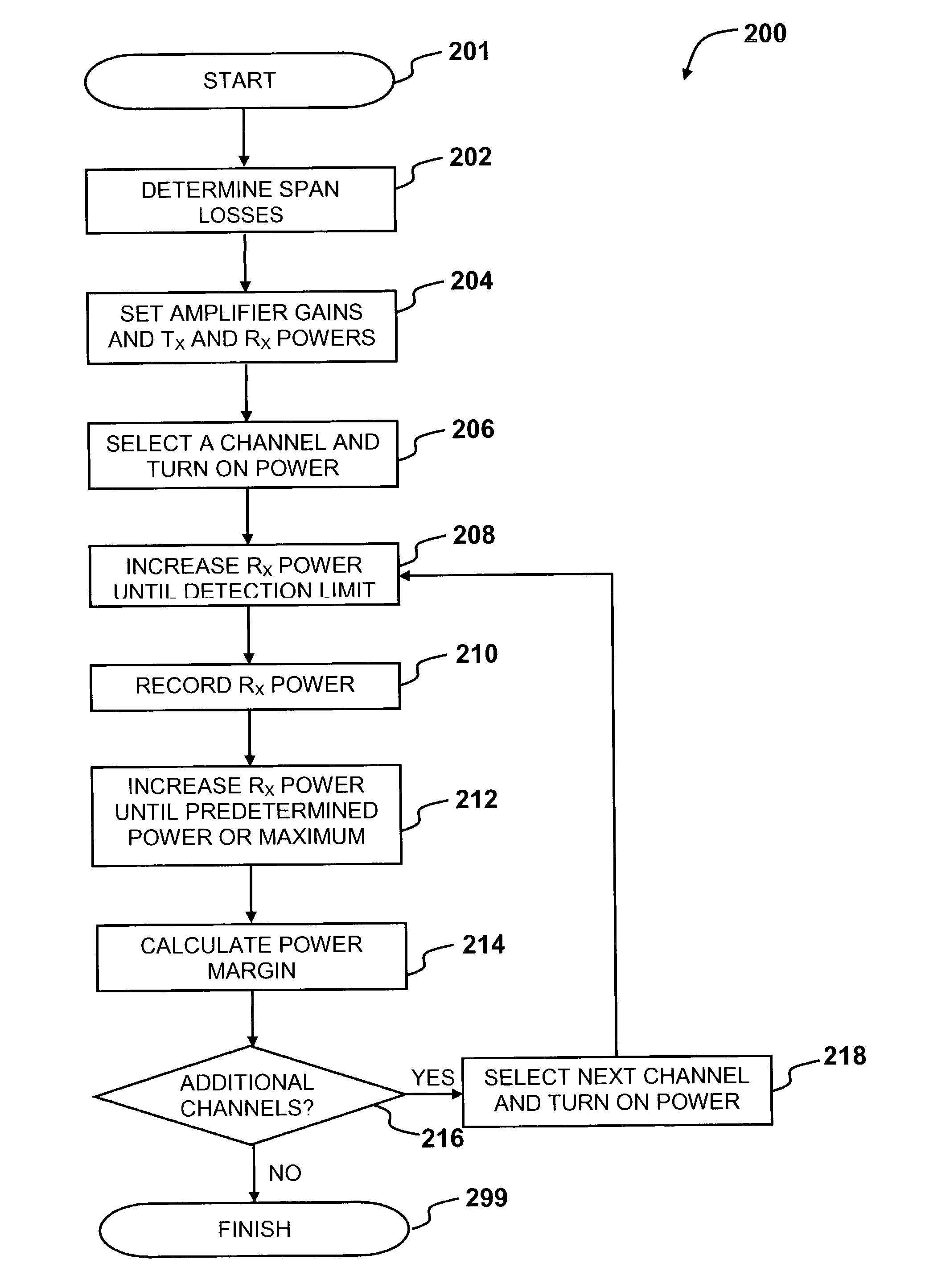
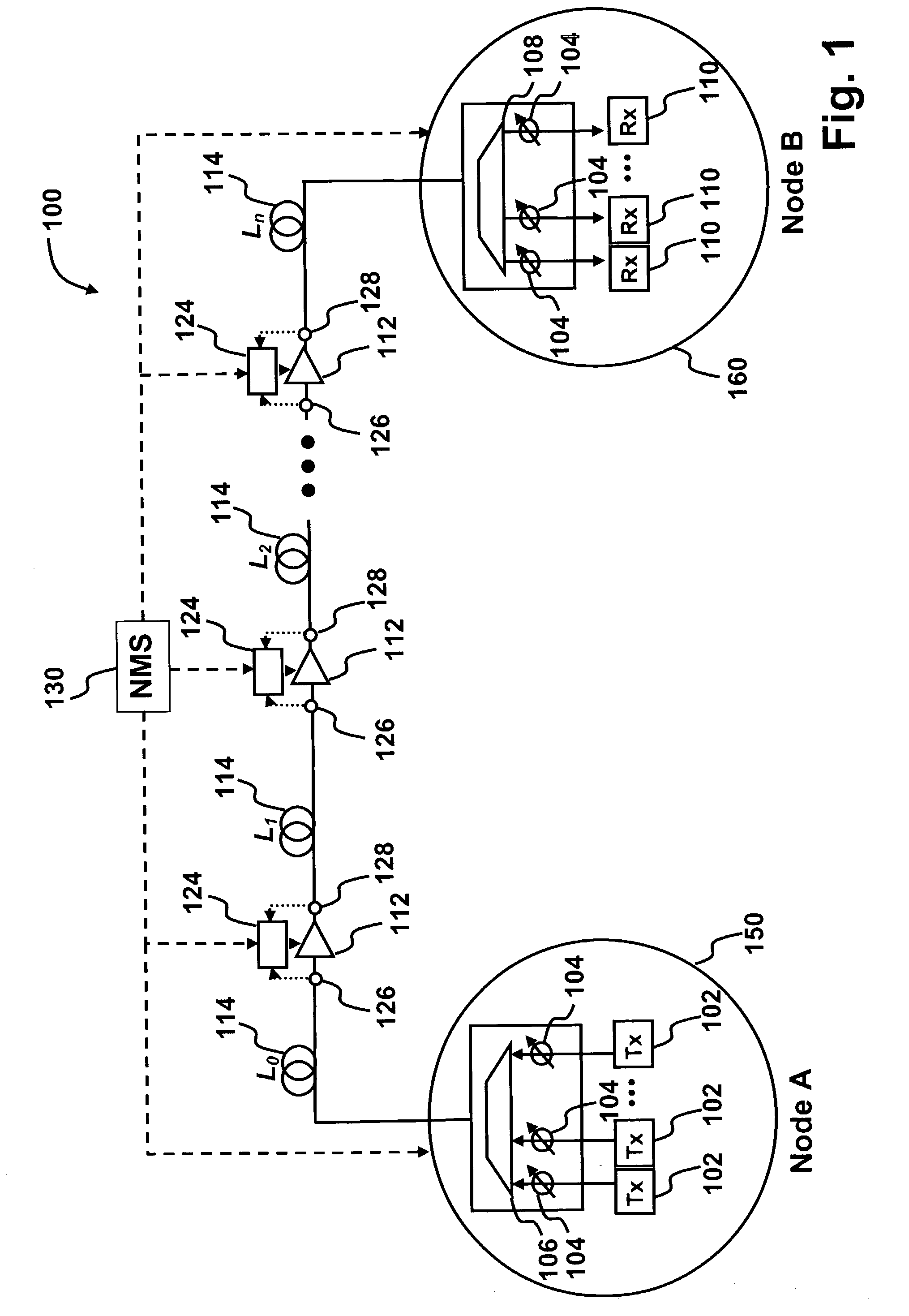
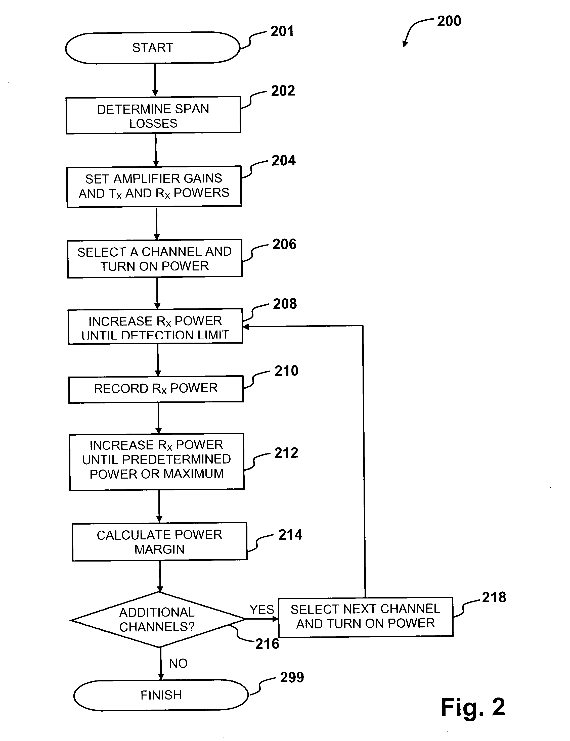
[0097]FIG. 2 is a flowchart 200 illustrating the steps of the method for initialization of an optical link in the optical network 100 according to the invention. The initialization method is performed on one optical link at a time, wherein each optical link is a path of a channel from one of the transmitters 102 on Node “A”150 to one of the corresponding receivers 110 on Node “B”160. The optical network 100 illustrated in FIG. 1 has a single optical link as was mentioned above.

[0098]Upon start 201, the procedure 200 performed by the NMS 130 determines the span loss of each fiber span 114 in the optical link (step 202). Remote, automatic methods of determining the span loss will be described in detail below.

[0099]In the step 204 of FIG. 2, the procedure 200 performed by the NMS 130 sets the target gain of each optical amplifier 112 and the signal power level at each transmitter 102 (Tx) and receiver 110 (Rx).

[0100]The signal power level at each transmitter 102 is set to be substantia...

second embodiment

[0118]According to the invention, the step 420 of FIG. 4 is applied after the step 218 in which the procedure 400 selects and turns on channel power to the next channel to be initialized. In the step 420 of FIG. 4, the procedure 400 performed by the NMS 130 applies gain excursion minimization (GEM) to the amplifiers 112 in the link in the following manner. The input and output channel powers are measured by the input and output channel power monitors 126 and 128 respectively to determine channel gains, which are the ratios of the output to input channel powers. The feedback control loop on each amplifier 112 dynamically supplies the automatic gain controlled amplifier 112 with a target gain calculated by the controller 124 to minimize or eliminate channel gain excursion. The target gain is calculated by the controller 124 according to the methods detailed in U.S. Pat. No. 10 / 195,495 to Ng et al. filed Jul. 16, 2002 and entitled “Method and Apparatus for Gain Excursion Minimization i...

third embodiment

[0120]According to the invention, the step 422 of FIG. 4 is added after all channels on the optical link have been initialized. In the step 422 of FIG. 4, the procedure 400 performed by the NMS 130 determines the power variation for different channels due to cumulative gain ripple of the amplifiers in the optical link and adjusts the signal power levels at the transmitters and / or the attenuations of attenuators at the transmitters so that the power variation at the transmitters is opposite to the cumulative gain ripple of the amplifiers in the link, the cumulative gain ripple being a variation of the amplifiers cumulative gain profile with channel wavelength. This adjusting of signal power levels to compensate for the effects of amplifier gain ripple is referred to as pre-emphasis and it minimizes the deleterious effects of power variation on the optical link. It may be implemented by, for example, adjusting the signal power levels of the channels so that they are substantially equa...


PUM


Abstract

A method for automatic initialization of an optical network is provided. A network management system (NMS) performs remote determination of span losses and sets the operating points of network components. The initialization method comprises remotely and automatically setting target gains of optical amplifiers and signal power levels at transmitters and receivers to required operating values. The methods for initialization of the optical network of the embodiments include gain excursion minimization (GEM) for individual channels passing through amplifiers and / or pre-emphasis of the optical link, where channel powers at the transmitters are biased to compensate for the effects of optical amplifiers gain ripple.

Description

RELATED APPLICATIONS[0001]This application claims benefit of U.S. Provisional Patent Application to Ng et al, Ser. No. 60 / 348,612 filed on 17 Jan. 2002; and of U.S. Provisional Patent Application to Ng et al, Ser. No. 60 / 354,025 filed on 5 Feb. 2002; U.S. Provisional Application to Wan et al, Ser. No. 60 / 365,779 filed on 21 Mar. 2002; and of U.S. Provisional Patent Application to Ng et al, Ser. No. 60 / 365,791 filed on 21 Mar. 2002; and of U.S. Patent Application to Ng et al, Ser. No. 10 / 195,495 filed on 16 Jul. 2002 entitled “Method and Apparatus for Gain Excursion Minimization in Automatic Gain Controlled Optical Systems”; and is related to a U.S. patent application to Ng et al, entitled “Method and System for Multi-Level Power Management in an Optical Network”, filed concurrently herewith.FIELD OF THE INVENTION[0002]The present invention relates generally to optical communications networks, and in particular to a method for automatic initialization of an optical network.BACKGROUND...

Claims


Application Information

Patent Timeline
Patent Type & Authority Patents(United States)
IPC IPC(8): H04B10/08H04B17/00H04B10/17
CPCH04B10/2942H04B10/2935
Inventor WAN, PING WAIREMEDIOS, DERRICKNG, EDDIE KAI HO
Owner WSOU INVESTMENTS LLC
Why Eureka
Try Eureka