Hydraulic circuit for backhoe

Inactive Publication Date: 2006-07-04
KUBOTA LTD
View PDF15 Cites 26 Cited by
  • Summary
  • Abstract
  • Description
  • Claims
  • Application Information

AI Technical Summary

Benefits of technology

[0008]The present invention addresses to the above-described problem. In the art pertaining to a hydraulic circuit for a backhoe which uses first and second pumps whose flow amounts are controlled (load sensing controlled) and a third pump for swiveling, and in which hydraulic drive of a front implement is effected under the control of a load sensing system, a primary object of the invention is to provide a hydraulic circuit which allows reduction in the size of the first and second pumps and renders the supply amount of the pressure oil to the traveling unit valve sections appropriate and which also restricts undesired reduction in the rising speed of the boom at the time of start-up of swiveling operation when the swiveling operation of the swivel table and the lift-up operation of the front implement boom are effected at the same time, thereby to allow the operations to take place efficiently with improved maneuverability
[0020]Therefore, according to the present invention, the first pump and the second pump may be formed small and also the supply amount of the pressure oil to the traveling unit valve sections may be rendered appropriate. Moreover, since the pressure oil from the third pump is constantly and unilaterally supplied to the front implement valve section, unlike the conventional construction, there is no need for providing the pilot type selector valve for combining the oil for the third pump. Hence, the construction of the invention can contribute to simplification of the entire hydraulic circuit and its cost reduction.
[0021]In addition, when the driving of the front implement and the swiveling operation are to be effected at one time, it is possible to restrict disadvantageous deceleration in the movement of the front implement such as the lift-up movement of its boom. So that, with the improved maneuverability, the two operations can be effected in an efficient manner.

Problems solved by technology

Accordingly, in the first-mentioned case when the vehicle is to travel without any implement operation, with supply of the pressure oils to the left and right traveling unit valve sections, a flow-amount control scheme based on power control will cause the first and second pumps to output flow amounts which, when combined, exceeds the required amount for traveling, thus tending to invite overheating and / or excessive rise in temperature of the work oil.
The provision of such valve invites cost increase.
In addition, in the case of the above-described backhoe hydraulic circuit, if a swiveling operation of a swivel table and a lift-up operation of a boom for the front implement are effected at one time, a significant inertia of the swivel table at the time of its activation will cause a rise in the start-up pressure, so that the flow amounts of the first and second pumps are reduced by the pump power control scheme, thus resulting in disadvantageous reduction in the rising speed of the boom.

Method used


Image

  • Hydraulic circuit for backhoe
  • Hydraulic circuit for backhoe
  • Hydraulic circuit for backhoe

Examples


Embodiment Construction

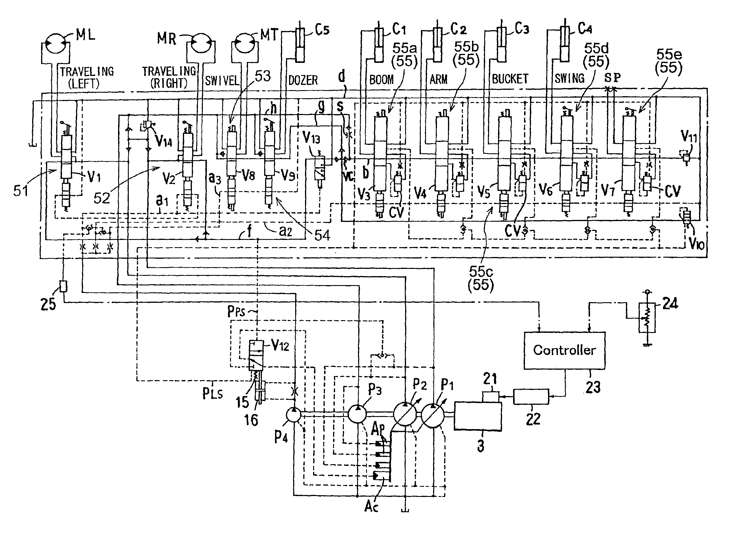
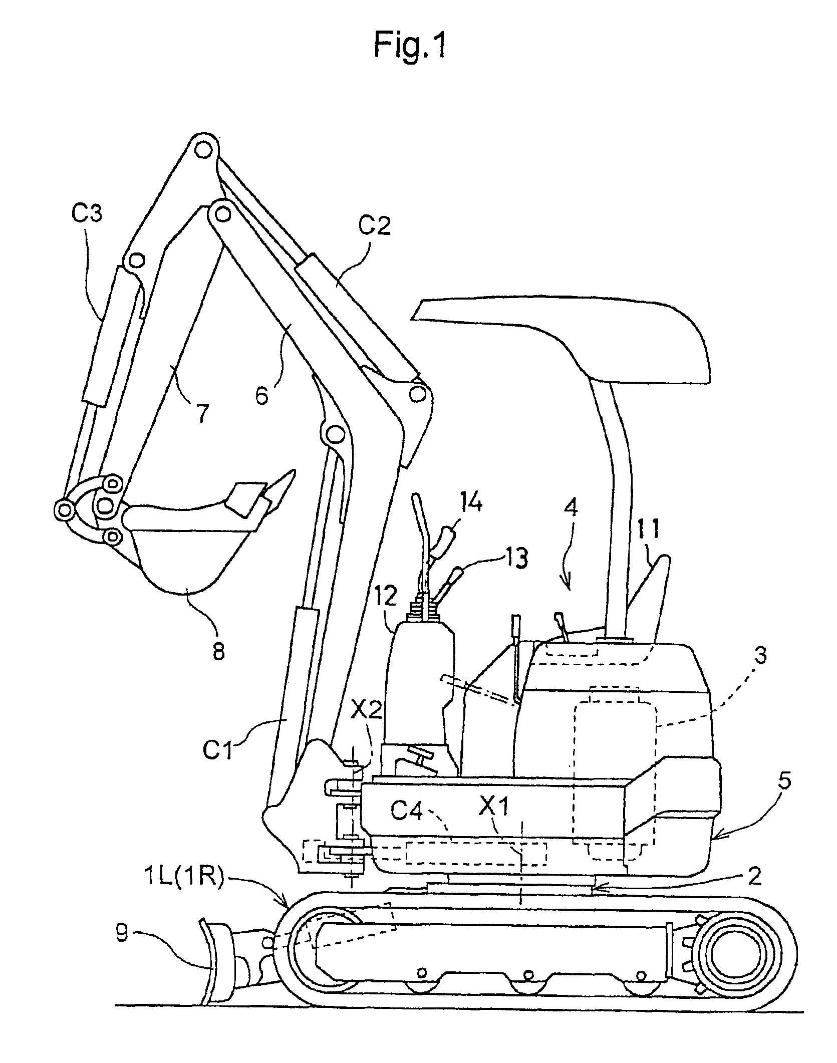
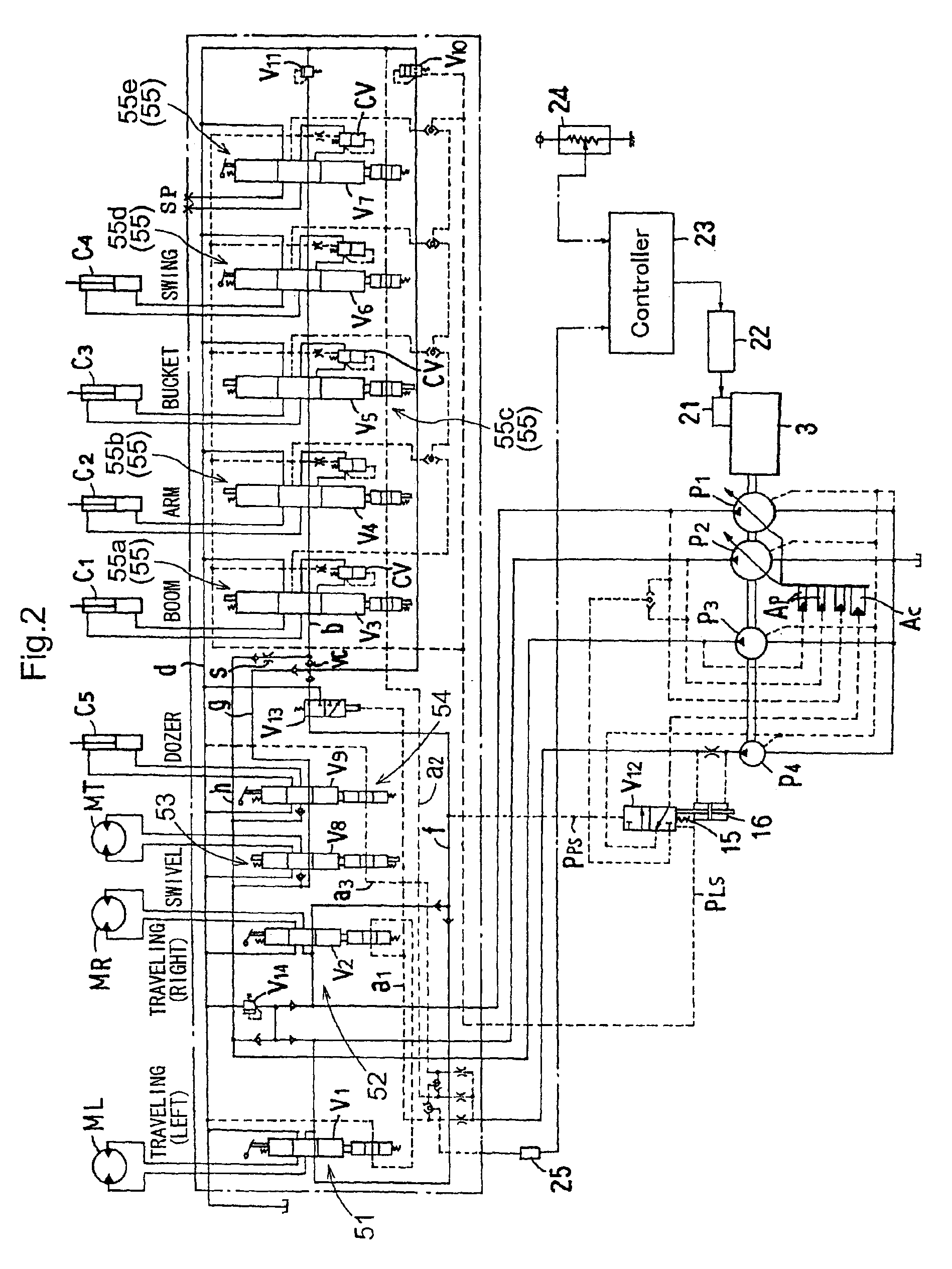
[0029]FIG. 1 is an overall side view of a backhoe implementing a hydraulic circuit according to the present invention. In this backhoe, on top of a traveling vehicle chassis 2 mounting a pair of left and right crawler type traveling units 1L, 1R, a swiveling table 5 mounting an engine 3 and a driver's section 4 is disposed to be capable of total-angle swiveling movement about a vertical axis X1. To the front of this swivel table 5, there is mounted a front implement 9 including a boom 6, an arm 7 and a bucket 8 interconnected in series. Further, an excavator plate 10 for dozer operation is attached to the front of the traveling vehicle chassis 2.

[0030]The left and right traveling units 1L, 1R are driven forwardly and reversely by traveling hydraulic motors ML, MR, respectively. The swivel table 5 is driven to be swiveled to the left or the right by a swiveling hydraulic motor MT. The boom 6, the arm 7 and the bucket 8 together constituting the front implement 9 are driven respective...


PUM


Abstract

A hydraulic circuit for use with a backhoe includes first, second and third pumps; left and right traveling unit valve sections-receiving pressure oil from the first and second pumps independently of each other; a front implement valve section receiving combined pressure oil including oil from respective center oil passages of the left and right traveling unit valve sections; and a swiveling valve section receiving pressure oil from the third pump. A parallel oil passage having a restrictor extends parallel to a center oil passage of the swiveling valve section. The front implement valve section also receives pressure oil from the center oil passage of the swiveling valve section and the parallel oil passage. A load sensing system controls flow amounts of the first and second pumps according to a hydraulic load generated in a front implement operation.

Description

BACKGROUND OF THE INVENTION[0001]1. Field of the Invention[0002]The present invention relates to a hydraulic circuit for a backhoe including a load sensing system for controlling pump flow amounts according to a sensed load.[0003]2. Description of the Related Art[0004]The above-described type of hydraulic circuit for a backhoe having a load sensing system is known from the Japanese Patent Application “Kokai” No. 2000-206256. According to the backhoe hydraulic circuit disclosed by this reference, when the backhoe is to travel without being accompanied by any implement operation, pressure oils respectively from a first pump and a second pump are supplied independently to a left traveling valve section and a right traveling valve section for driving left and right traveling units. When only a front implement for excavating operation is to be operated with keeping the backhoe still (i.e. under non-traveling condition), the pressure oils from the first and second pumps are combined to be...

Claims


Application Information

Patent Timeline
IPC IPC(8): E02F5/02F16D31/02E02F3/34E02F9/22F15B11/00F15B11/17
CPCE02F3/325E02F9/2235E02F9/2296E02F9/2292E02F9/2242
Inventor ARII, KAZUYOSHI
Owner KUBOTA LTD
Why Eureka
Try Eureka