Power assisted steering for all terrain vehicle

a technology for all terrain vehicles and steering wheels, applied in the direction of power driven steering, fluid steering, vehicle components, etc., can solve problems such as creating a very edgy or twitchy riding experien

Inactive Publication Date: 2006-07-04
YAMAHA MOTOR CO LTD
View PDF44 Cites 17 Cited by
  • Summary
  • Abstract
  • Description
  • Claims
  • Application Information

AI Technical Summary

Benefits of technology

[0023]A further aspect of the present invention involves a power steering system for use on an all terrain vehicle. The power steering system comprises a power steering cylinder comprising a cylinder body defining a pair of cylinder chambers separated by a piston. A piston rod extends from the cylinder body and is connected to the piston at one end and is operably connected to a steering column at another end. An input shaft of a power steering valve is adapted for connection to the power steering column. The power steering valve forms a portion of a closed loop power steering fluid system. The power steering valve further comprises a spool and an output shaft. The input shaft and the output shaft are connected with a torsion bar. The output shaft is adapted for connection to a steerable wheel. The spool is connected to the output shaft such that rotation of the output shaft relative to the input shaft results in the power steering valve opening and flow in the closed loop being directed into or out of the cylinder chambers to effect movement of the piston rod. The closed loop power steering system further comprises a bypass passage that diverts flow from around the spool valve. A flow regulator is disposed within the bypass passage and a controller is adapted to control the flow regulator depending upon a sensed vehicle operating speed and a sensed differential lock mode.

Problems solved by technology

As will be appreciated, providing a constant level of power assist for turning at low speeds as at high speeds would likely create a very edgy or twitchy riding experience.

Method used


Image

  • Power assisted steering for all terrain vehicle
  • Power assisted steering for all terrain vehicle
  • Power assisted steering for all terrain vehicle

Examples


Embodiment Construction

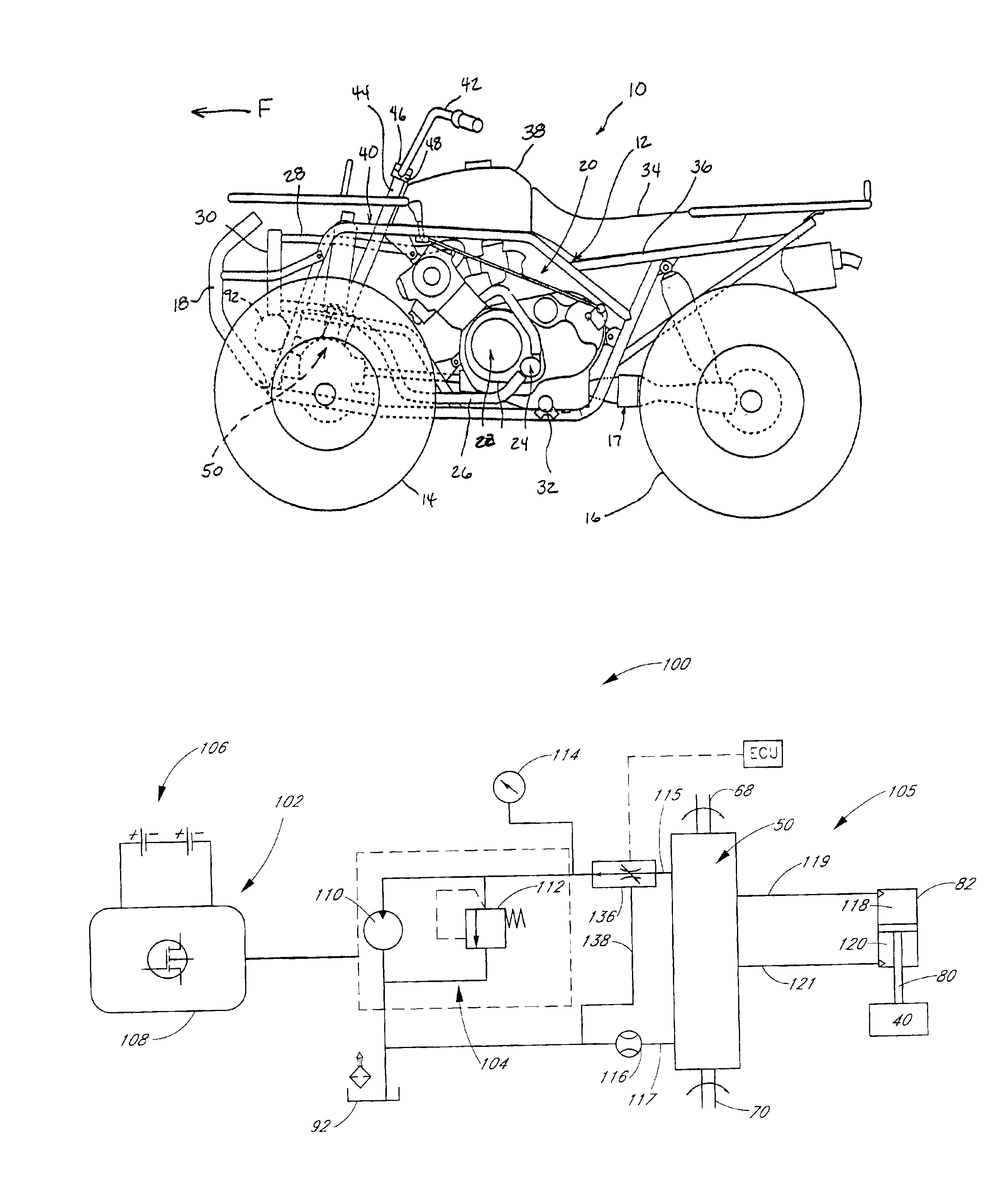
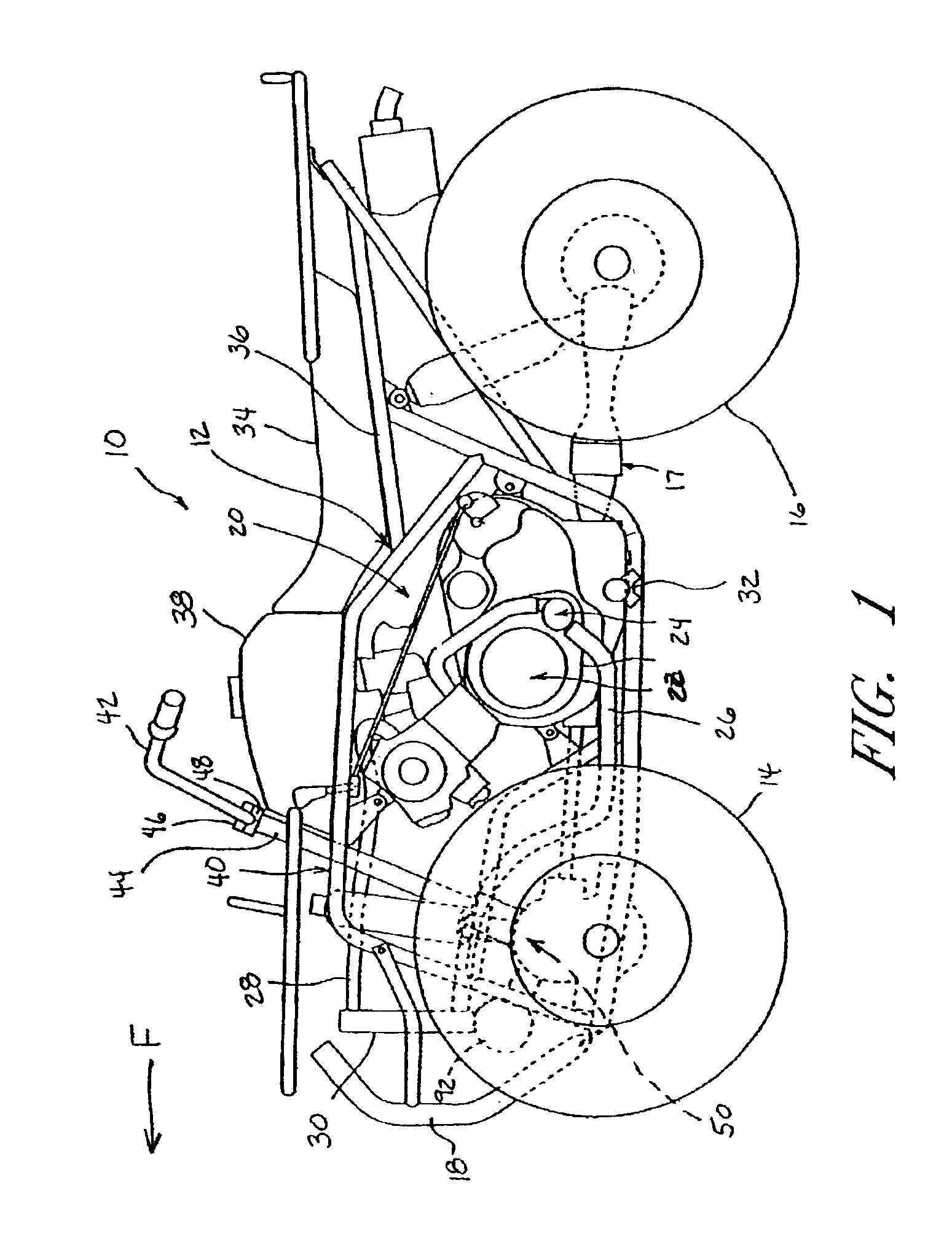
[0033]With reference initially to FIG. 1, a recreational all terrain vehicle, which is generally indicated by the reference numeral 10, has been designed and configured to employ a power assisted steering arrangement that can be arranged and configured in accordance with certain features, aspects and advantages of the present invention. While the present power assisted steering arrangement will be described in the context of a four wheeled recreational all terrain vehicle, it is anticipated that certain features, aspects and advantages of the present power assisted steering arrangement also can be used with other light duty vehicles. Certain features, aspects and advantages of the present invention also can be used in vehicles featuring two or more sets of steerable wheels.

[0034]With continued reference to FIG. 1, the illustrated vehicle 10 generally comprises a frame assembly 12 that is supported by two sets of wheels. In the illustrated arrangement, a pair of front wheels14 are co...


PUM


Abstract

An all terrain vehicle has a frame carried by a group of wheels. At least one of the wheels is steerably connected to the frame. A steering handle assembly is rotatably connected to the frame. A servo valve has an input shaft connected to the steering handle assembly and an output shaft connected to a pitman arm. A linkage extends from the pitman arm to the steerable wheel or wheels. A pump draws fluid from a reservoir and passes the fluid through the servo valve before the fluid is returned to the reservoir. The servo valve redirects at least a portion of the flow to a cylinder to drive a ram within the cylinder in response to steering movement of the steering handle assembly. The ram, in turn, provides a power assist to the steerable wheel or wheels. A variable speed, constant displacement pump can be used to vary the flow rate in a manner that reduces the flow rate as the vehicle speed increases. Alternatively, a bypass can be used to vary a flow rate through the servo valve. A damping valve arrangement also can be provided to absorb shocks to the steering system such that the wheels can initially deflect and then return to the original position without substantial input from the steering handle assembly.

Description

RELATED APPLICATIONS[0001]This application is related to and claims the priority benefit of U.S. Provisional Patent Application No. 60 / 299,946, filed on Jun. 21, 2001, which is hereby incorporated by reference in its entirety.BACKGROUND OF THE INVENTION[0002]1. Field of the Invention[0003]The present invention generally relates to all terrain vehicles. More particularly, present invention relates to recreational all terrain vehicles having power assisted steering arrangements useful to facilitate low speed steering and steering with a locked differential as well as to reduce high-speed steering kick-back caused by glancing blows to steerable wheels.[0004]2. Description of the Related Art[0005]All terrain vehicles currently are undergoing a transformation. Previously, the vehicles were rather simple in design, relatively low powered and featured few rider comforts associated with larger motor vehicles, such as automobiles. Recently, however, riders have been demanding more of their r...

Claims


Application Information

Patent Timeline
Patent Type & Authority Patents(United States)
IPC IPC(8): B62D5/00B62D5/12B62D6/02
CPCB62D6/02B62D5/12
Inventor TAKAMOTO, DAVID T.AULD, JACK R.DUNNE, JR., JOHN C.DUPRE, III, HARRY ADAMANDERFAAS, ERIC N.BANKS, DEAN W.MOTT, GREGORY E.
Owner YAMAHA MOTOR CO LTD
Why Eureka
Try Eureka