
Breathable seat

a seat and breathable technology, applied in the field of breathable seats, can solve the problems of not being able to enjoy the necessary hardness of a cushion body, being unable to achieve given dimensions, and conventional seats cannot be satisfactorily prevented from becoming non-breathable, and achieve good cushioning properties

Inactive Publication Date: 2006-07-04
NHK SPRING CO LTD
View PDF15 Cites 127 Cited by
  • Summary
  • Abstract
  • Description
  • Claims
  • Application Information

AI Technical Summary

Benefits of technology

[0008]Accordingly, the object of the present invention is to provide a breathable seat capable of being satisfactorily prevented from becoming nonbreathing and enjoying good cushioning properties.
[0010]The breathable seat of the invention can be satisfactorily prevented from being rendered nonbreathing by a user's perspiration or the like and can enjoy good cushioning properties.
[0011]If the seat body is supported by means of a pan frame having apertures, according to the invention, the apertures should be aligned individually with the venting holes. By doing this, the damping force of the seat can be proportioned to the gross sectional area of the venting holes in some measure, so that it can be set with ease.
[0012]Preferably, the gas permeability of the seat cover is 10 cc / cm2 / sec or more. If the diameter of each continuous linear element ranges from 0.1 to 1.0 mm, the touch of the surface of the seat is improved.

Problems solved by technology

When the seat is removed from a mold, the fibrous layer is released from the foaming pressure of the urethane foam and restored, so that it cannot obtain given dimensions.
Since the seat cannot easily obtain a satisfactory foaming pressure, moreover, it cannot enjoy necessary hardness for a cushion body.
However, these conventional seats cannot be satisfactorily prevented from becoming nonbreathing and cannot readily enjoy good cushioning properties.

Method used


Image

  • Breathable seat
  • Breathable seat
  • Breathable seat

Examples


Embodiment Construction

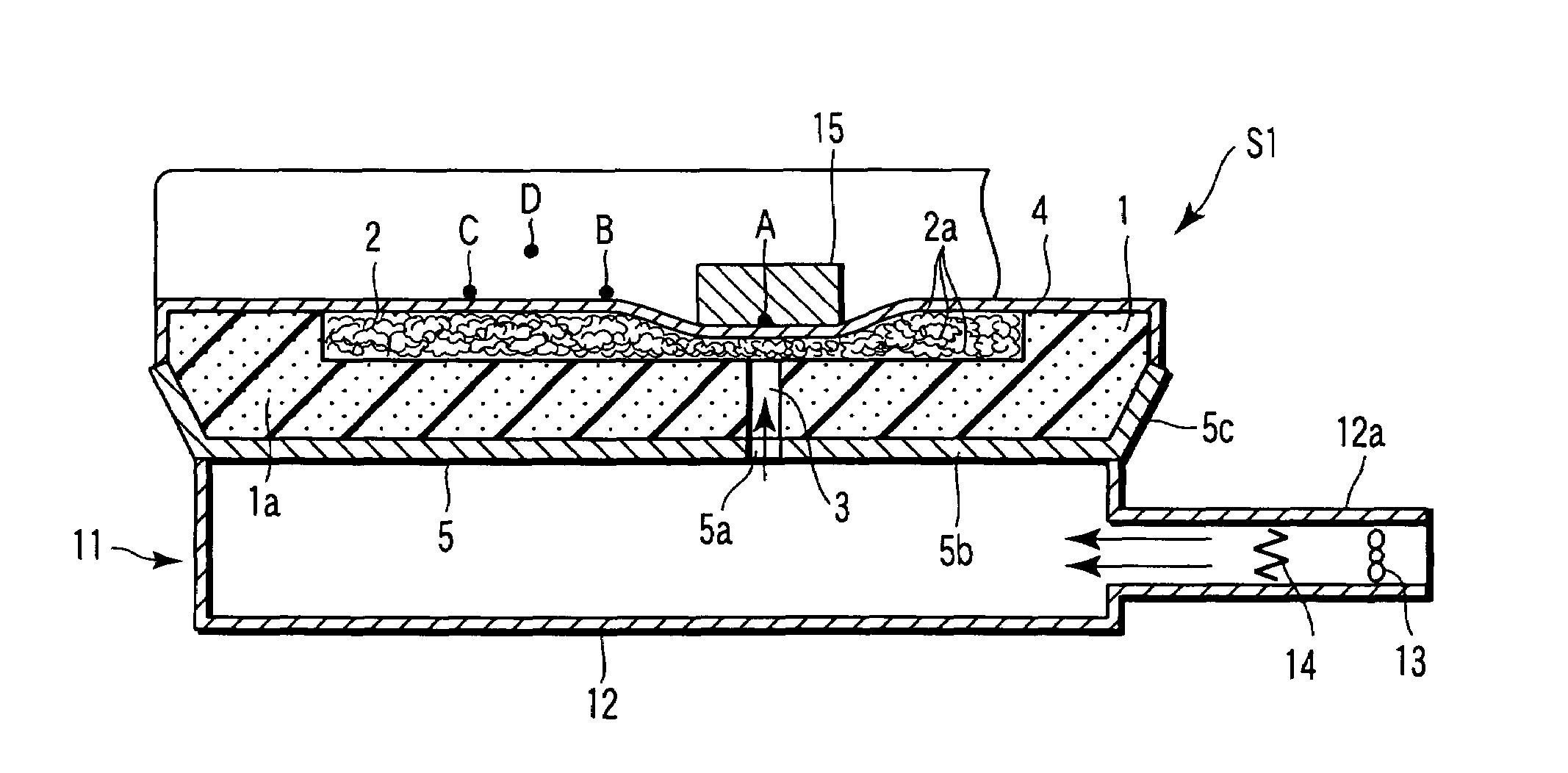
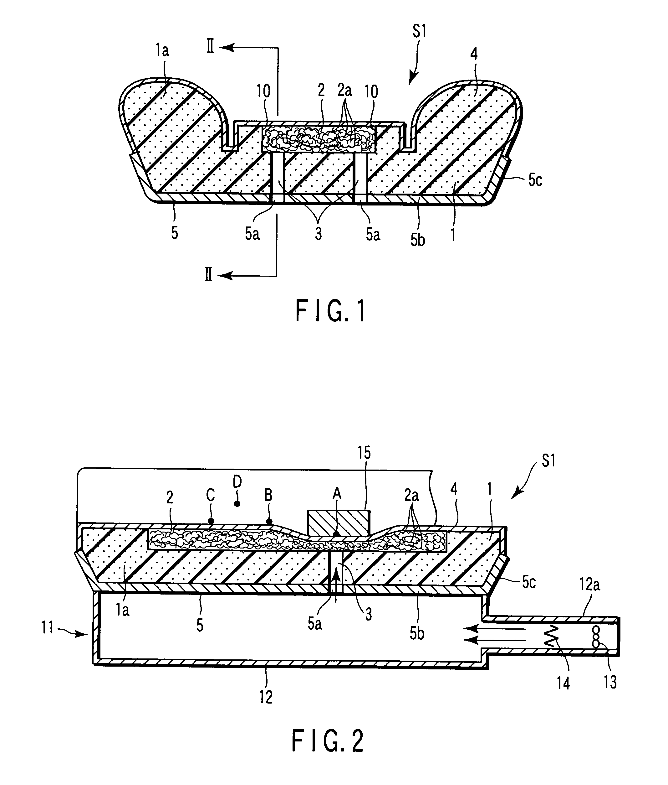
[0027]A breathable seat according to a first embodiment of the present invention will now be described with reference to FIGS. 1 to 4. A breathable seat S1 shown in FIG. 1 comprises a seat body 1 formed of urethane foam 1a, a three-dimensional network cushion body 2, a seat cover 4 having breathability, and a pan frame 5 that supports the seat body 1. The cushion body 2 is incorporated in that region of the seat body 1 which bears a user's body. The pan frame 5 has a bottom wall 5b in the form of a plate and a sidewall 5c that is formed around the bottom wall 5b. The breathable seat 51 is used for a seat cushion of a vehicle seat, for example.

[0028]At least two venting holes 3 are formed in the urethane foam 1a that constitutes the seat body 1. The holes 3 extend in the thickness direction of the foam 1a (or in the vertical direction of FIG. 1) and open into the three-dimensional network cushion body 2. The urethane foam 1a, which is a continuous foam, in general, has gas permeabili...


PUM


Abstract

A breathable seat comprises a seat body formed of urethane foam, a three-dimensional network cushion body incorporated in that region of the seat body which bears a user's body, a seat cover having breathability, and a pan frame. The cushion body is formed of a large number of continuous linear elements of thermoplastic resin. The linear elements are looped windingly so that their respective contact portions are fused together. The seat body is formed having venting holes that penetrate the urethane foam in its thickness direction. The venting holes communicate with the cushion body and apertures of the pan frame. The seat cover envelops the seat body and the cushion body.

Description

CROSS-REFERENCE TO RELATED APPLICATIONS[0001]This application is based upon and claims the benefit of priority from the prior Japanese Patent Application No. 2002-236961, filed Aug. 15, 2002, the entire contents of which are incorporated herein by reference.BACKGROUND OF THE INVENTION[0002]1. Field of the Invention[0003]The present invention relates to breathable seats used for seats, chairs, etc. in means of transportation, such as cars, watercraft, aircraft, etc.[0004]2. Description of the Related Art[0005]Described in Jpn. Pat. Appln. KOKOKU Publication No. 4-14848 (prior art 1) and Jpn. UM Appln. KOKOKU Publication No. 6-12688 (prior art 2) are breathable seats that are formed of a fibrous cushion (fibrous layer) and urethane foam molded integrally with each other. In the seat described in the prior art 1, the fibrous layer is pushed by a foaming pressure that is produced as a stock solution of urethane foam is injected for molding. When the seat is removed from a mold, the fibr...

Claims


Application Information

Patent Timeline
IPC IPC(8): A47C7/74A47C7/18A47C7/62A47C27/12A47C27/14B60N2/56B60N2/58B60N2/90
CPCA47C7/18B60N2/5891B60N2/5657B60N2/5628B60N2/5664
Inventor MINEGISHI, TAKESHIKIKUCHI, KAZUOEBIHARA, TAKASHI
Owner NHK SPRING CO LTD
Learn More