Light source device and projection display

a technology of projection display and light source device, which is applied in the direction of projection device, lighting and heating apparatus, instruments, etc., can solve the problems of insufficient light utilization efficiency of display, inability to provide a projection display commercially bright enough for practical use, and difficulty in reducing the size and weight of the overall display, etc., to achieve good white balance and high light utilization efficiency

Inactive Publication Date: 2006-07-04
NEC DISPLAY SOLUTIONS LTD
View PDF16 Cites 120 Cited by
  • Summary
  • Abstract
  • Description
  • Claims
  • Application Information

AI Technical Summary

Benefits of technology

[0012]The present invention has been made to solve the drawbacks of the prior art mentioned above, and it is an object of the invention to provide a light source device and a projection display which exhibit a good white balance and a high light utilization efficiency in consideration of the light emission efficiencies inherent to individual light emitting diodes.
[0013]The invention is intended to provide a light source device which is advantageous in the arrangement of light emitting diodes over the conventional light source device using a cross dichroic mirror, realizes an ideal white balance and a high light utilization efficiency, and further improves the light utilization efficiency through polarization conversion of illumination beams, which are randomly polarized light, from the light emitting diodes.
[0014]The invention also is intended to provide a light source device which can be significantly reduced in size.
[0015]The invention is further intended to provide a light source device which can be further reduced in weight.

Problems solved by technology

In addition, due to large amount of heat generated by the light source itself, a cooling fan must be used to manage the temperature of the lamp and a cooling condition for the two-dimensional image device when the lamp is on.
These requirements make it difficult to reduce the size and weight of the overall display.
However, a light source composed of light emitting diodes or laser diodes, as in the aforementioned prior art examples, disadvantageously fails to commercially provide a projection display bright enough for practical use due to a lack of luminance produced by each light emitting element.
Particularly, when a dichroic mirror is used in a projection display as disclosed in JP-2002-244211-A and JP-2000-56410-A, a limitation is imposed to locations available for disposing R, G, B light emitting diodes, giving rise to the following problems.
Even if the same number of light emitting diodes are provided in the respective channels, all the light emitting diodes cannot be used in such a manner that the maximum optical power can be produced in each of the channels.
For this reason, even if a cross dichroic prism is specially used in favor of a reduction in size, a resulting display disadvantageously suffers from an insufficient light utilization efficiency because it cannot utilize the maximum power from the maximum number of available light emitting diodes provided in each channel.

Method used


Image

  • Light source device and projection display
  • Light source device and projection display
  • Light source device and projection display

Examples


first embodiment

(First Embodiment)

[0035]FIG. 3 is a schematic diagram illustrating a first embodiment of a light source device. In FIG. 3, reference numerals 101, 102 designate light emission boards on which a plurality of light emitting diodes are two-dimensionally arranged. Reference numerals 103, 104 designate polarized light forming means. Reference numeral 105 designates a polarizing beam splitter.

[0036]Randomly polarized light emitted from the light emitting diodes on light emission boards 101, 102 is uniformly converted to P-polarized light or S-polarized light by polarized light forming means 103, 104 before it is incident on polarizing beam splitter 105. An illumination beam emitted from the light emitting diodes on light emission board 101 and uniformly converted to S-polarized light is reflected on polarized light separation surface 106 of polarizing beam splitter 105, and exits from polarizing beam splitter 105. On the other hand, an illumination beam emitted from the light emitting dio...

second embodiment

(Second Embodiment)

[0042]FIG. 4 is an explanatory diagram for a second embodiment which illustrates an exemplary modification to the light source device described in the first embodiment. The second embodiment differs from the first embodiment in that wire grid type polarizer 205 is used for combining illumination beams from two light emission boards 201, 202 in FIG. 4.

[0043]Known wire grid type polarizers include ProFlux (registered trademark) from MOXTEK Inc., U.S.A., and the like. ProFlux (registered trademark) is a grid type polarizer which has a fine Al grid formed on a glass substrate, which has a width of approximately 65 nm, a height of 100–200 nm, and a pitch of approximately 140 nm, and transmits a polarized light component of randomly polarized light incident thereon in a vibrating direction orthogonal to the longitudinal direction of the grid, and reflects a polarized light component in a vibrating direction parallel with the longitudinal direction of the grid. This type...

third embodiment

(Third Embodiment)

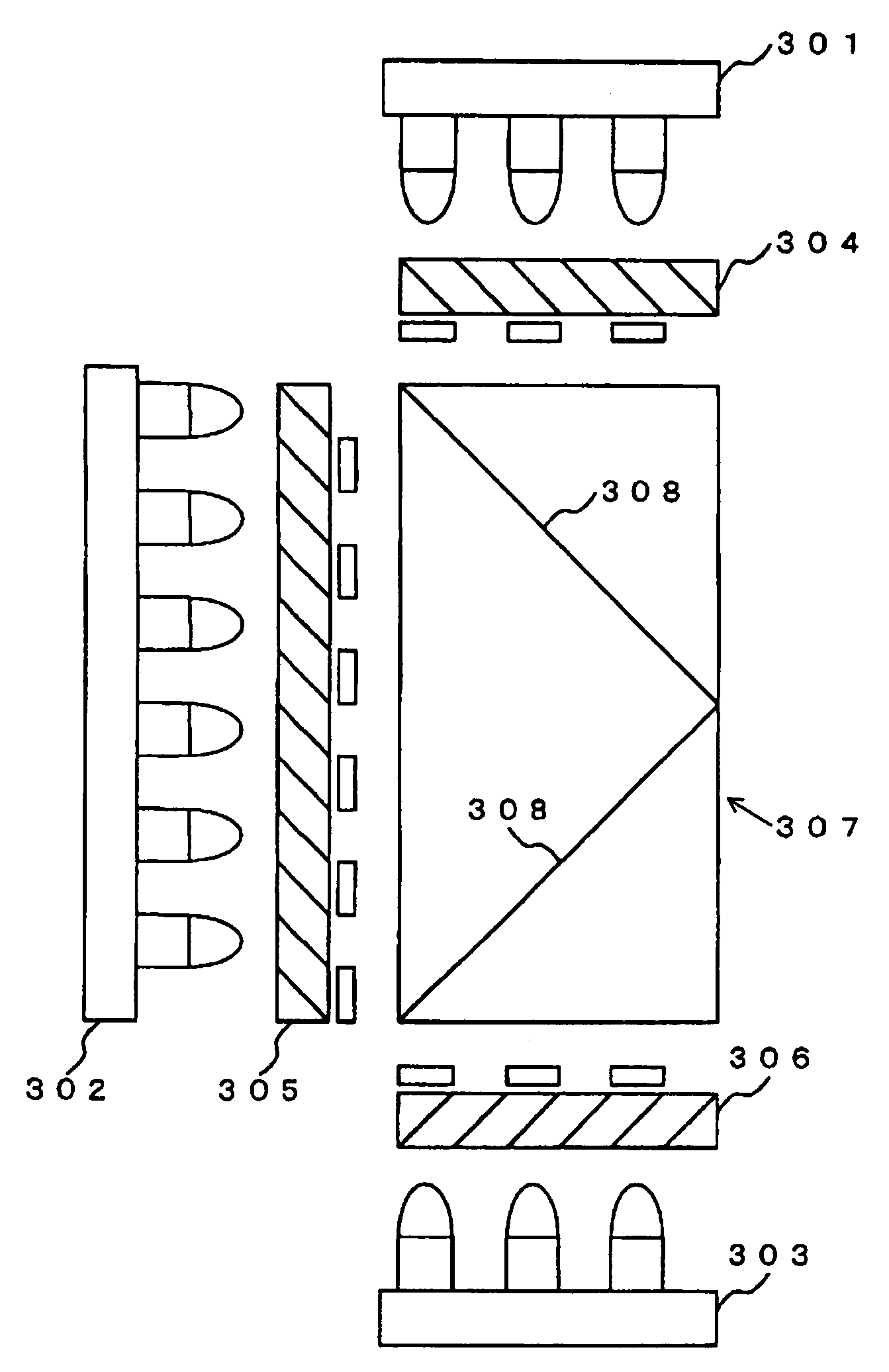
[0045]FIG. 5 is an explanatory diagram for a third embodiment which illustrates another exemplary modification to the light source device described in the first embodiment. The third embodiment differs from the first embodiment in that a light source device in FIG. 5 comprises three light emission boards 301, 302, 303, and polarizing beam splitter 307 having a V-shaped polarized light separation surface 308 for combining illumination beams from three light emission boards 301, 302, 303. The resulting light source device is reduced in volume to one half, and therefore is much smaller than the light source device of the first embodiment which employs polarizing beam splitter 105.

[0046]Randomly polarized light emitted from light emitting diodes arranged on light emission boards 301, 302, 303 is uniformly converted by polarized light forming means 304, 305, 306, respectively, to P-polarized light or S-polarized light which is incident on polarizing beam splitter 307. I...


PUM


Abstract

A light source device which employs a plurality of light emitting diodes for emitting different colors of light, and a projection display which incorporates the light source device provide for a good white balance and a high light utilization efficiency in consideration of light emission efficiencies inherent to the respective color light emitting diodes. An illumination beam from each of light emission boards is converted to one type of polarized light respectively by associated polarized light forming means, and resulting polarized light beams are combined by a polarizing beam splitter to produce an illumination beam for illuminating a two-dimensional image device which may comprise a digital mirror device (DMD). The light emitting diodes in the respective colors are arranged on respective light emission boards in a predetermined ratio of distribution to optimize the white balance.

Description

BACKGROUND OF THE INVENTION[0001]1. Field of the Invention[0002]The present invention relates to a light source device and a projection display, and more particularly to a light source device which employs a plurality of light emitting diodes for a light source, and a projection display which incorporates the light source device.[0003]2. Description of the Related Art[0004]Conventional projection displays typically comprise a light source using a single high-pressure mercury lamp which irradiates an illumination beam therefrom to three or one two-dimensional image device for modulating an image. The modulated image is enlarged and displayed on a screen using a projection lens. The high-pressure mercury-arc lamp, which serves as the light source, is a white lamp that has light emission characteristics from an ultraviolet region to an infrared region, and a dichroic mirror, a rotary color filter, or the like is used to select wave-length components of R (red), G (green), B (blue) ligh...

Claims


Application Information

Patent Timeline
Patent Type & Authority Patents(United States)
IPC IPC(8): G03B21/14G02B27/28G03B21/00H04N9/31
CPCH04N9/3197H04N9/315
Inventor KATO, ATSUSHI
Owner NEC DISPLAY SOLUTIONS LTD
Why Eureka
Try Eureka