Reverse chamfer and countersink tool

a countersink cutter and reverse chamfer technology, applied in the field of countersink cutters, can solve the problems of limited access to fasteners, user's lack of countersink stop tools for applications, and the predetermination of the depth at which the countersink cutter penetrates the workpiece,

Active Publication Date: 2006-07-04
LOCKHEED MARTIN CORP
View PDF37 Cites 5 Cited by
  • Summary
  • Abstract
  • Description
  • Claims
  • Application Information

AI Technical Summary

Benefits of technology

[0008]One embodiment of a reverse chamfering and countersink stop tool constructed in accordance with the present invention allows the required diameter of a countersink in a workpiece to be maintained in areas that have limited accessibility for the user assembling a fastener to the workpiece. The tool controls the dimension required for proper installation of fasteners under such conditions. The tool can also be used for other applications that require control of the diameter of a chamfer. The tool allows the diameter of the chamfer / countersink to be set outside the point of use for maintaining proper tolerances. The present design utilizes a modified reverse countersink cutter that is captured inside an externally threaded adjustable stop housing. The captured cutter is movable both axially and rotationally, and is driven by a drill equipped with a pilot. The stop position of the cutter is controlled by a series of nuts that are located and threaded on the exterior of the housing.

Problems solved by technology

In particular, countersink devices predetermine the depth at which a countersink cutter penetrates the workpiece.
Currently, the user does not have a countersink stop tool for applications wherein access to the fasteners is limited visually and / or physically.
However, users are still required to visually inspect or verify the finished workpiece to determine if the countersink depth is acceptable, which can be a very inconsistent process.
Indeed, most countersink devices are engaged by power tools through a rear end of the device (i.e., through an end opposite the cutting end) such that the power tools require a significant amount of operating space behind the countersink device.
Some formations in workpieces have such limited access, both physically and visually, that this arrangement is unworkable.
This is an unacceptable design for many applications because the rotating stop deforms or scuffs the surface of the workpiece.
During normal use, the cutters will become worn and must be refurbished or replaced.
However, the cutters cannot be re-sharpened because the dimension from the cutter to the stop would be altered, thereby rendering the tool useless.

Method used


Image

  • Reverse chamfer and countersink tool
  • Reverse chamfer and countersink tool
  • Reverse chamfer and countersink tool

Examples


Embodiment Construction

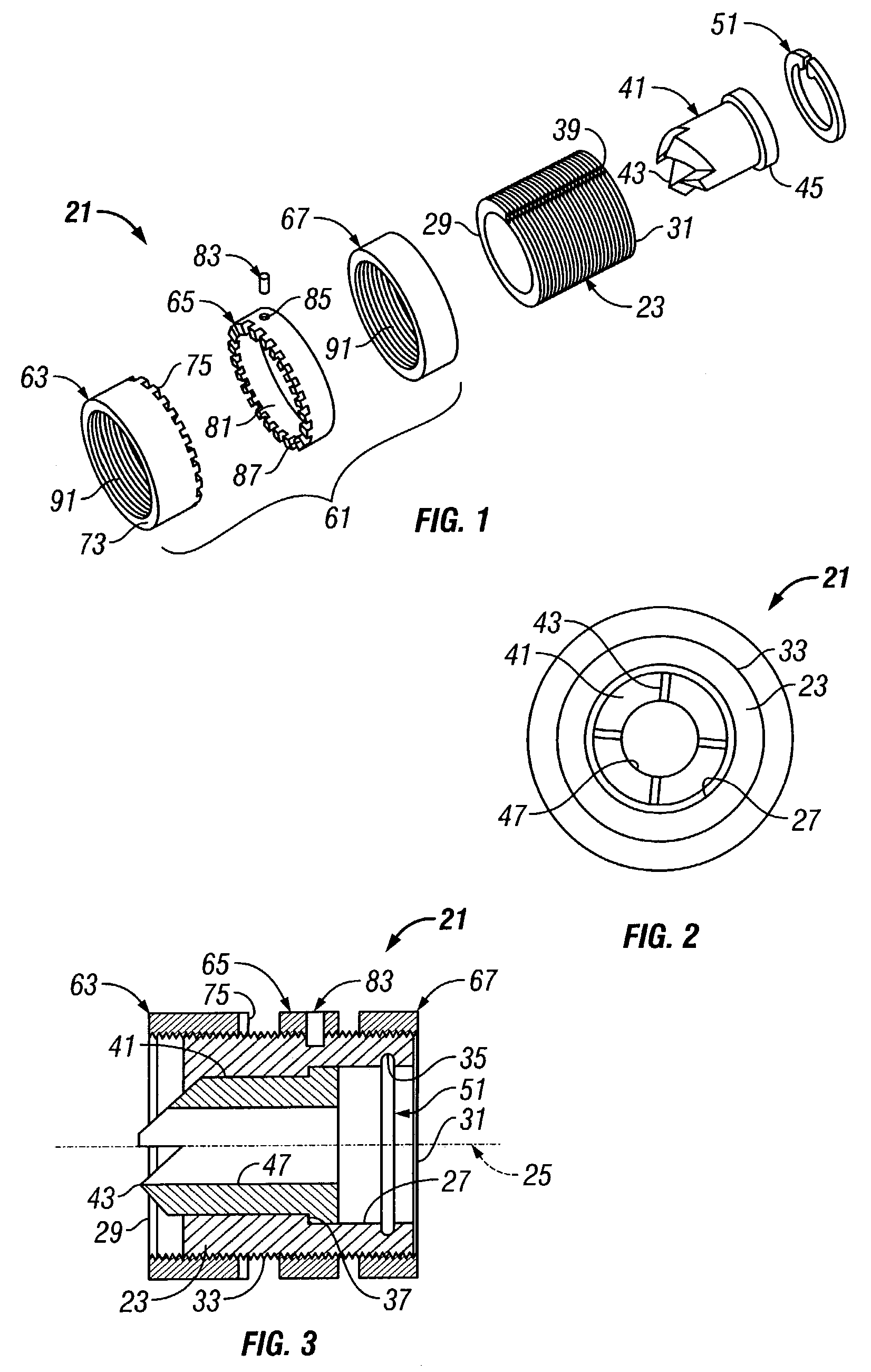
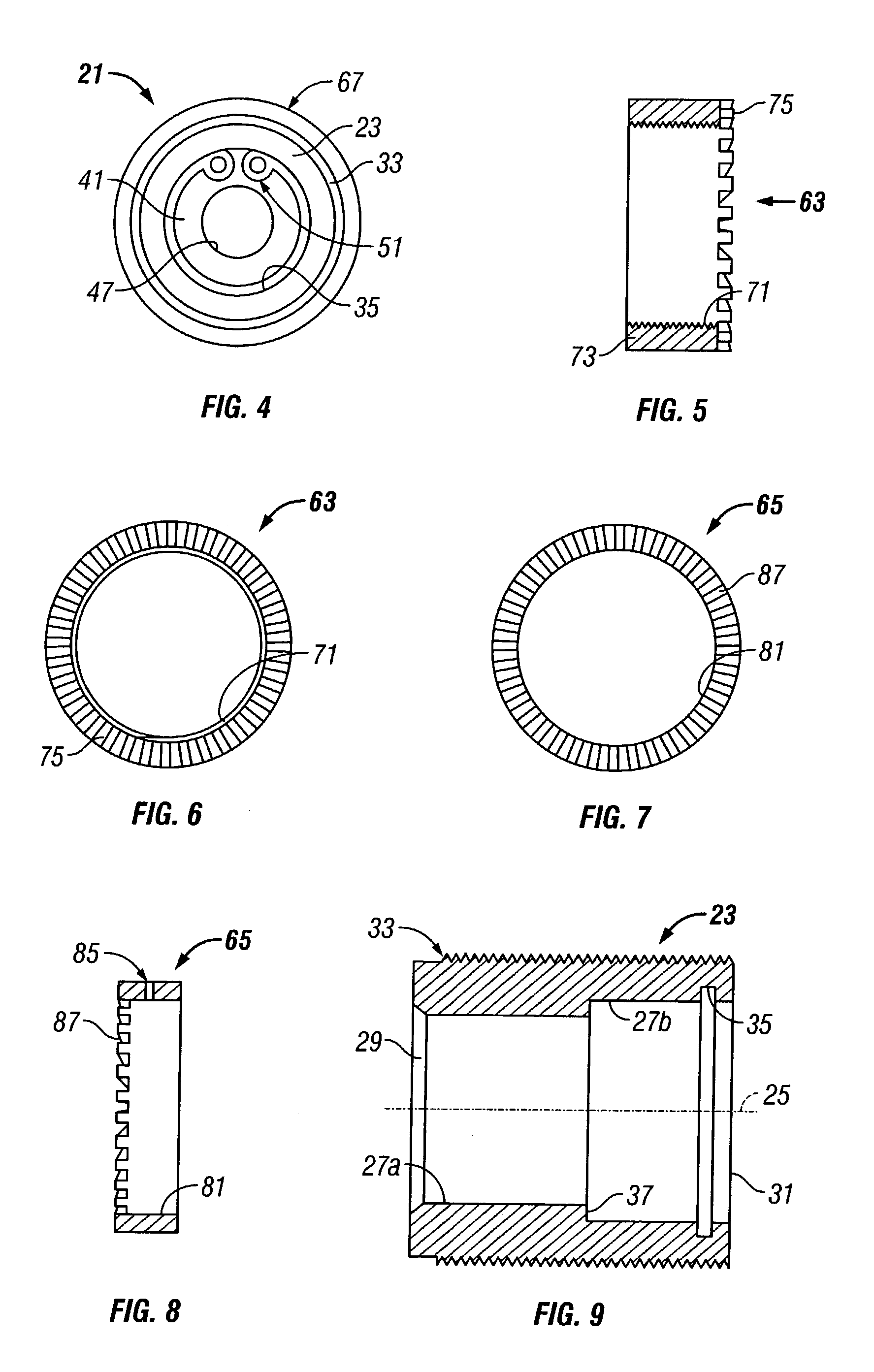
[0026]Referring to FIGS. 1–4, one embodiment of a tool 21 constructed in accordance with the present invention is shown. Tool 21 comprises a number of different components that are assembled and used to together to form tool 21. For example, in the embodiment shown, tool 21 comprises a generally tubular housing 23, which is best shown in FIGS. 9 and 10. Housing 23 has an axis 25 and a cylindrical bore 27 (defined by two different diameters, 27a and 27b) extending axially through the housing 23. A cutting opening 29 is formed on one end of the housing 23 at bore 27, and a loading opening 31 is formed on an opposite end thereof. The housing 23 also has an external surface with threads 33 formed thereon. A seat 35 is located in the bore 27 and comprises an annular recess. A shoulder 37 is also located in the bore 27, such that the bore 27 has at least the two diameters 27a, 27b, defined on opposite axial sides of shoulder 37. In addition, a slot 39 extends axially along the external su...


PUM

PropertyMeasurementUnit
relative rotationaaaaaaaaaa
dimensionaaaaaaaaaa
depthaaaaaaaaaa

Abstract

A reverse chamfering and countersink stop tool allows the required diameter of a countersink in a workpiece to be maintained in areas that have limited accessibility for the user assembling a fastener to the workpiece. The tool controls the dimension required for proper installation of fasteners under such conditions. The tool can also be used for other applications that require control of the diameter of a chamfer, and allows the diameter of the chamfer/countersink to be set outside the point of use for maintaining proper tolerances. The tool utilizes a modified reverse countersink cutter that is captured inside an externally threaded adjustable stop housing. The captured cutter is movable both axially and rotationally, and is driven by a drill equipped with a pilot. The stop position of the cutter is controlled by a series of nuts that are located and threaded on the exterior of the housing.

Description

[0001]This invention was made with Government support under Contract Number F33657-99-C-0036 awarded by The Department of the Air Force. The Government has certain rights in this invention.BACKGROUND OF THE INVENTION[0002]1. Technical Field[0003]The present invention relates in general to an improved countersink tool, and in particular to an improved tool for forming countersinks in locations on workpieces that are obstructed or difficult to access.[0004]2. Description of the Related Art[0005]Devices for forming countersinks in workpieces are common in the prior art. A wide variety of countersink devices are commercially available and commonly used in many different manufacturing and assembly processes. Countersink devices are particularly helpful in quickly forming countersink and / or chamfer features in workpieces, and doing so at with precise dimensions. In particular, countersink devices predetermine the depth at which a countersink cutter penetrates the workpiece. In order to ac...

Claims


Application Information

Patent Timeline
Patent Type & Authority Patents(United States)
IPC IPC(8): B23B35/00B23B49/00B23B51/10
CPCB23B49/005B23B51/102B23B2260/004Y10T408/564Y10T408/03Y10T408/5621Y10T408/18
Inventor WEARE, MARK A.
Owner LOCKHEED MARTIN CORP
Why Eureka
Try Eureka