Compact compression connector for spiral corrugated coaxial cable

a compression connector and coaxial cable technology, applied in the direction of coupling device connection, two-part coupling device, electrical apparatus, etc., can solve the problems of affecting signal quality, difficult for those in the art to design connectors or connection techniques, and difficult to correctly make such connections without requiring labor intensive effort of highly skilled technicians. , to achieve the effect of simple and effective utilization

Inactive Publication Date: 2006-07-04
JOHN MEZZALINGUA ASSOC INC
View PDF19 Cites 173 Cited by
  • Summary
  • Abstract
  • Description
  • Claims
  • Application Information

AI Technical Summary

Benefits of technology

[0009]These and other needs are met by the present invention, which provides a compression connector for coaxial cable. By way of non-limiting example, the coaxial cable can be spiral corrugated coaxial cable that has a center conductor surrounded by a dielectric layer, which, in turn, is surrounded by a plurality of conductive corrugations. A groove (e.g., a continuous groove) is defined between the corrugations, wherein the corrugations are at least partially surrounded by a protective outer cable jacket. The connector of the present invention can be advantageously utilized with spiral corrugated coaxial cable because the connector provides strong contact forces against the cable, yet is simple and effective to utilize in either factory or field installation settings.

Problems solved by technology

In general, it has proven difficult to correctly make such connections without requiring labor intensive effort by highly skilled technicians.
Moreover, even if careful attention is paid during installation, there still can be installation errors, which, in turn, can moderately to several affect signal quality.
These generalized installation problems are likewise encountered with respect to spiral corrugated coaxial cable (i.e., cable that is often referred to in the art as “Superflex” cable), which, however, also poses its own set of unique issues.
That, in turn, makes it difficult for those in the art to design connectors or connection techniques for engagement of the spiral corrugated coaxial cable in a manner that provides a high degree of mechanical stability, electrical shielding and environmental sealing yet that also is not physically damaging the irregular outer surface of the cable.
Although this methodology generally ensures that reliable mechanical and electrical connections are achieved, it also necessitates usage of highly specialized, unwieldy soldering equipment as well as the dedication of trained manpower to perform the soldering.
However, these benefits are more than overshadowed by various drawbacks, most notably the unreliability of the technique.
For example, the shielding that is achieved by contact forces created between the thread protrusion of the connector and the outer wall of the spiral corrugated coaxial cable can degrade over time.
Moreover, in order for the thread protrusion to be installable on the spiral corrugated coaxial cable there must be some clearance between it and the cable, and the only interference between the cable and the connector exists as a result of contact force generated by bottoming the cable in the connector against the course pitch threads of the cable and protrusion.
However, the contact force can become relaxed over time, due to one or more common conditions such as temperature fluctuations, vibrations, and flexure of the cable relative to the connector.
And if the contact force becomes relaxed, then the necessary interference is negated and, in turn, the connection between the cable and the connector is lost.

Method used


Image

  • Compact compression connector for spiral corrugated coaxial cable
  • Compact compression connector for spiral corrugated coaxial cable
  • Compact compression connector for spiral corrugated coaxial cable

Examples


Embodiment Construction

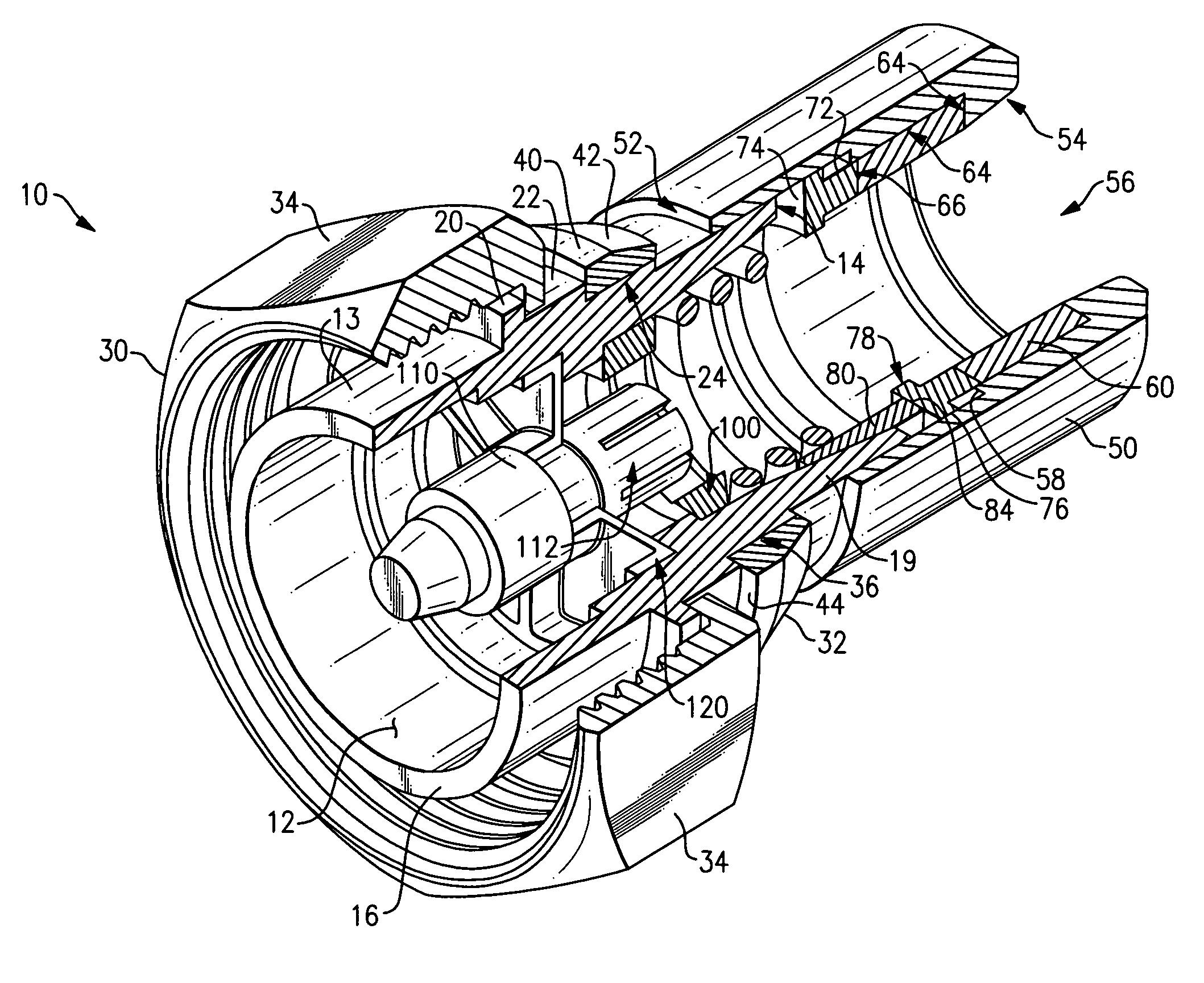
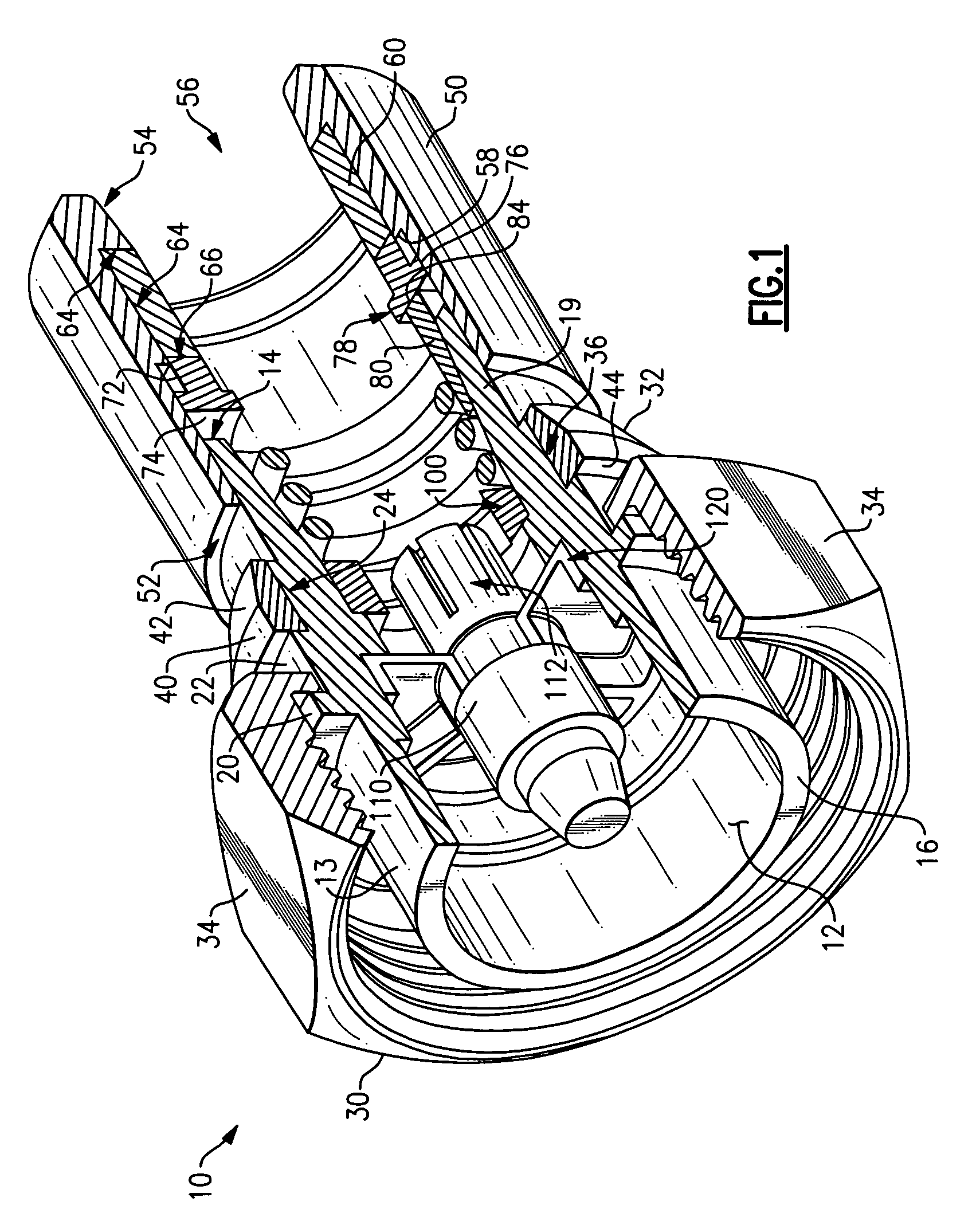
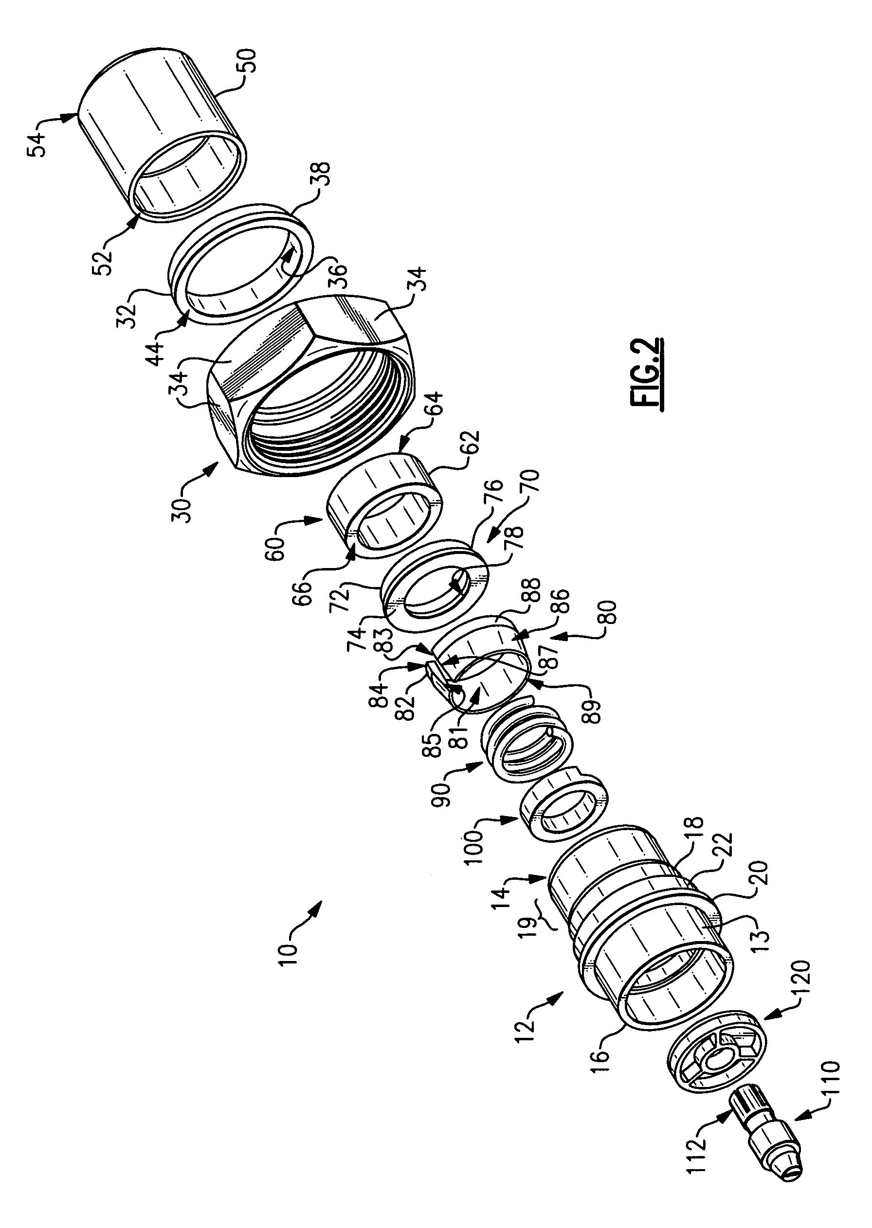
[0024]Referring initially to FIGS. 1 and 2, a compression connector 10 for spiral corrugated coaxial cable is illustrated. The compression connector 10 is advantageous in that it is simple to install in a factory or field setting and it is reliably effective at establishing and maintaining contact forces between the connector and the cable. Although the connector 10 is depicted in these figures as a DIN male connector interface, it is within the scope of the present invention for the connector to have other interfaces, including, but not limited to a BNC connector interface, a TNC connector interface, an F-type connector interface, an RCA-type connector interface, a DIN female connector interface, an N male connector interface, an N female connector interface, an SMA male connector interface, and an SMA female connector interface.

[0025]The compression connector 10 includes a connector body 12, which has a proximal end 14 and a distal end 16. In accordance with an exemplary embodimen...


PUM


Abstract

A compression connector for the end of a spiral corrugated coaxial cable is provided wherein one or more contact forces are provided between the connector and the cable by driving a coiled element of the connector into a groove within the corrugations of the cable and/or by causing an element of the compression connector to radially deform inward against the outer jacket of the cable.

Description

FIELD OF THE INVENTION[0001]This invention relates in general to terminals for coaxial cables, and, more particularly, to compact compression connectors for use with spiral corrugated coaxial cables.BACKGROUND OF THE INVENTION[0002]Coaxial cable is being deployed on a widespread basis in order to carry signals for communications networks, e.g., CATV and computer networks. All types of coaxial cable must at some point be connected to network equipment ports. In general, it has proven difficult to correctly make such connections without requiring labor intensive effort by highly skilled technicians. Moreover, even if careful attention is paid during installation, there still can be installation errors, which, in turn, can moderately to several affect signal quality.[0003]These generalized installation problems are likewise encountered with respect to spiral corrugated coaxial cable (i.e., cable that is often referred to in the art as “Superflex” cable), which, however, also poses its ...

Claims


Application Information

Patent Timeline
Patent Type & Authority Patents(United States)
IPC IPC(8): H01R9/05
CPCH01R24/564H01R4/5083H01R9/0518H01R2103/00H01R13/622
Inventor MONTENA, NOAH
Owner JOHN MEZZALINGUA ASSOC INC
Why Eureka
Try Eureka