Synchronous induction motor and electric hermetic compressor using the same

a technology of synchronous induction motor and electric hermetic compressor, which is applied in the direction of pulse technique, dynamo-electric converter control, magnetic circuit shape/form/construction, etc., can solve the problems of poor re-starting property and difficulty in fast cooling of electric hermetic compressor

Active Publication Date: 2006-07-04
PANASONIC APPLIANCES REFRIGERATION DEVICES SINGAPORE
View PDF17 Cites 25 Cited by
  • Summary
  • Abstract
  • Description
  • Claims
  • Application Information

AI Technical Summary

Benefits of technology

[0002]The present invention relates to a synchronous induction motor installed in a refrigerator, an air-conditioner or the like, and an electric hermetic compressor using the same.

Problems solved by technology

Additionally, the enlarged diameter of thermistor 13 increases the heat capacity of thermistor 13, causing difficulty in fast cooling.
Namely, a longer time is required to cool thermistor 13 to a temperature ready for re-starting, resulting in a poor re-starting property for the electric hermetic compressor.

Method used


Image

  • Synchronous induction motor and electric hermetic compressor using the same
  • Synchronous induction motor and electric hermetic compressor using the same
  • Synchronous induction motor and electric hermetic compressor using the same

Examples


exemplary embodiment 1

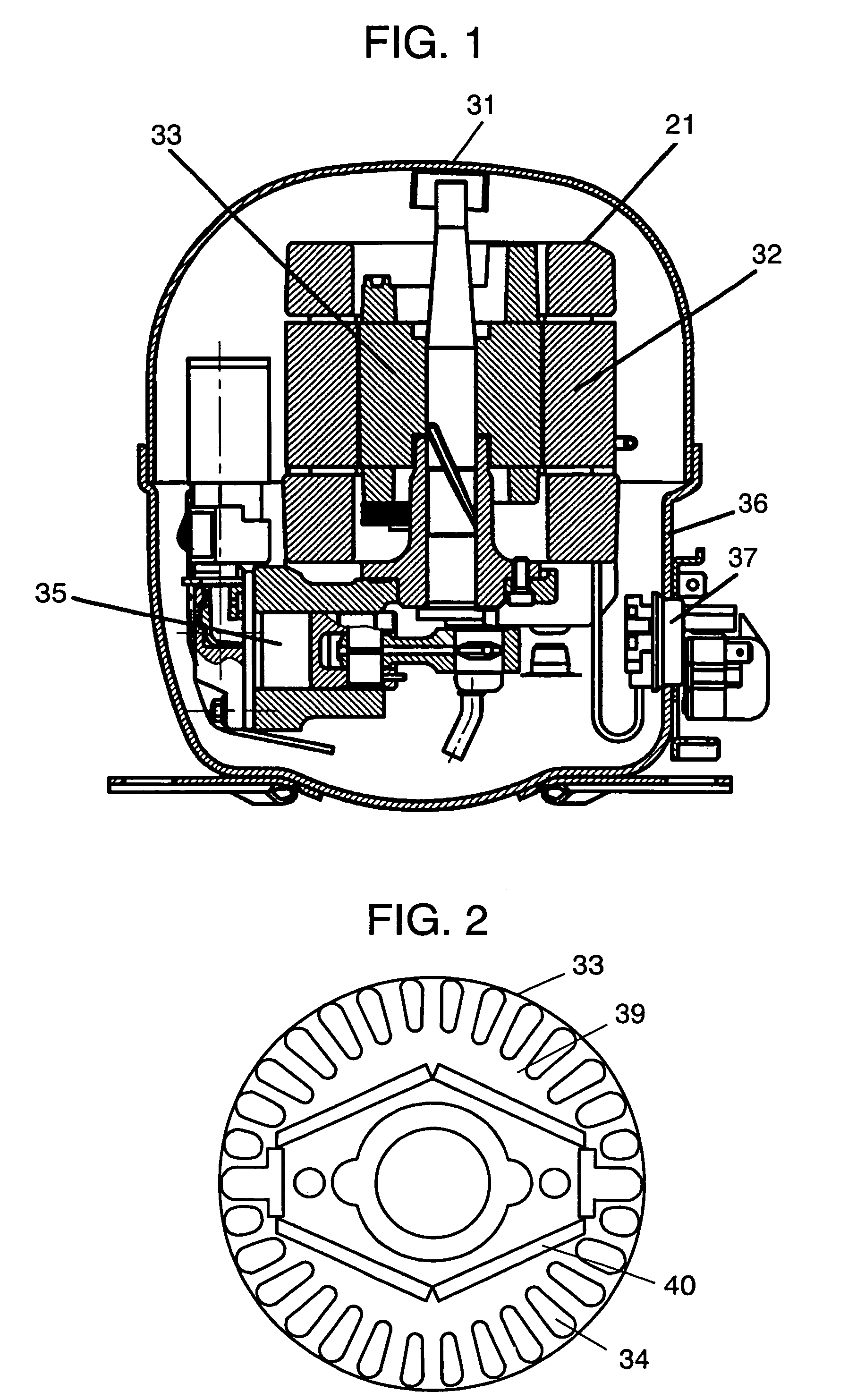
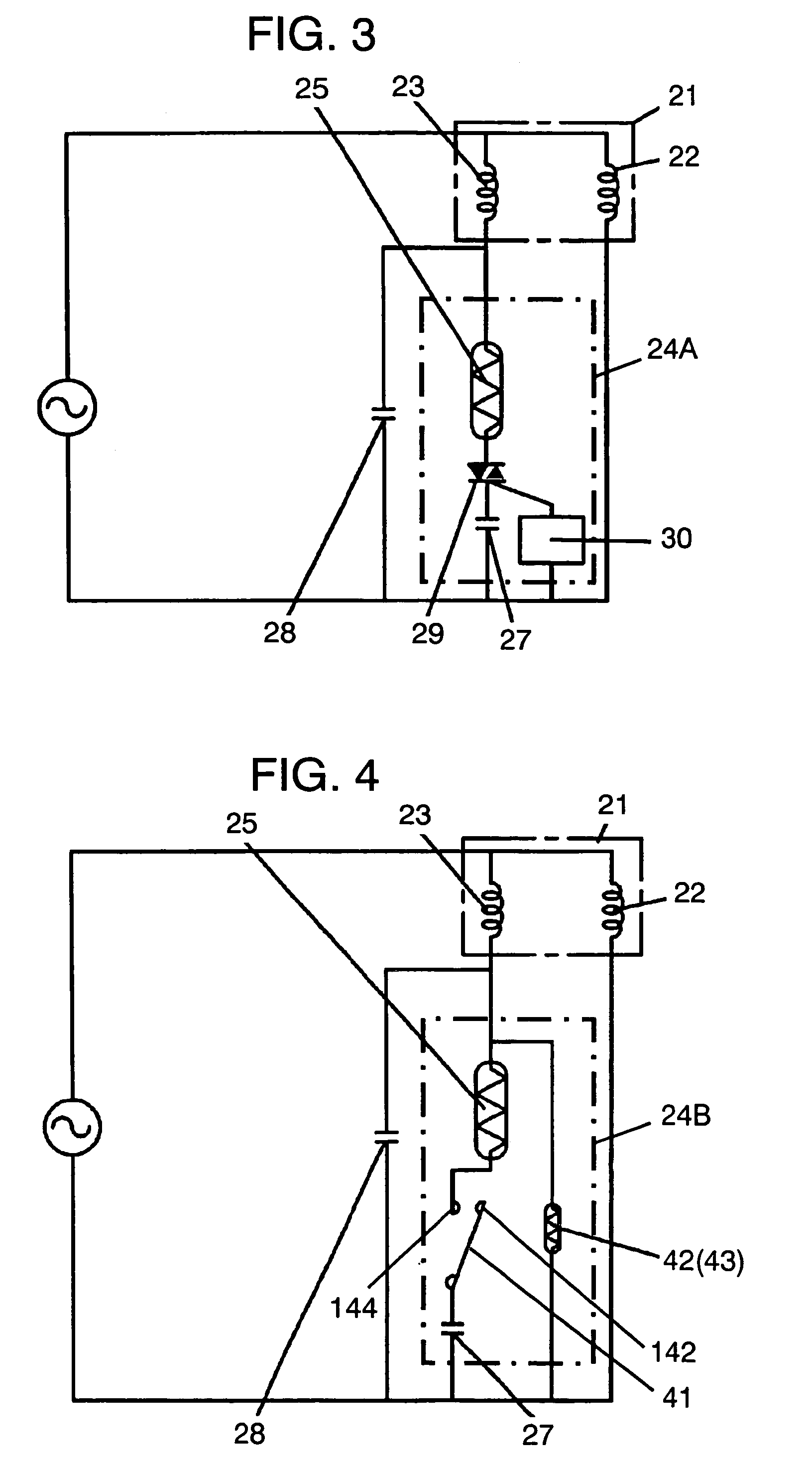
[0033]FIG. 1 is a cross-sectional view of an electric hermetic compressor according to an exemplary embodiment of the present invention, and FIG. 2 is a cross-sectional view of a rotor for the synchronous induction motor. FIG. 3 is a circuit diagram of the synchronous induction motor.

[0034]Hermetic housing 36 of electric hermetic compressor 31 contains synchronous induction motor 21 and compression unit 35 driven by motor 21. Motor 21 starts as an induction motor and runs as a synchronous induction motor to rotate in sync with a supply frequency at steady state running (operation). Motor 21 has stator 32 and rotor 33. Stator 32 has main winding 22 and auxiliary winding 23 wound on a core (not shown) made of steel sheet laminations. Rotor 33 encloses permanent magnets 40 in yoke 39 made also of steel sheet laminations and has aluminum-made secondary conductors 34 provided in the vicinity of the periphery of yoke 39.

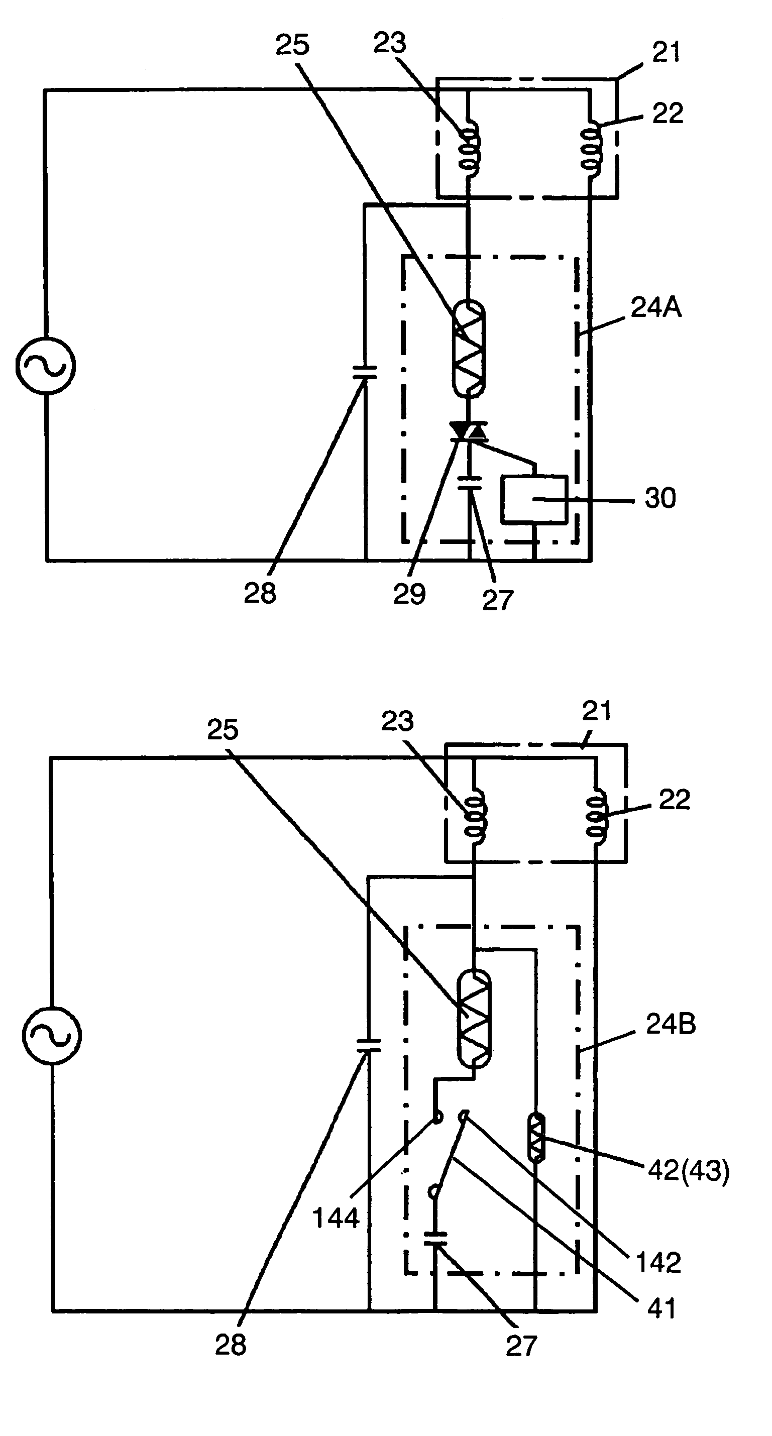
[0035]Auxiliary winding 23 is connected in series with positive tempe...

exemplary embodiment 2

[0042]FIG. 4 shows a circuit diagram of a synchronous induction motor used in a second exemplary embodiment of the present invention. As shown in FIG. 4, starter 24B includes thermistor 25, starting capacitor 27, bimetal switch 41, and auxiliary positive temperature coefficient thermistor (auxiliary thermistor) 42. Bimetal switch 41 is connected in series with thermistor 25 and starting capacitor 27. Auxiliary thermistor 42, connected electrically to auxiliary winding 23 and in parallel with bimetal switch 41 to act as a heating element, is coupled thermally with bimetal switch 41 to apply thermal effects on bimetal switch 41. A switching unit has bimetal switch 41 and auxiliary thermistor 42 in this configuration. Namely, starter 24B has thermistor 25, starting capacitor 27 and the switching unit. Components other than used in the configuration are the same as those used in the first exemplary embodiment.

[0043]Next, the operations of synchronous induction motor 21 and starter 24B w...

exemplary embodiment 3

[0055]FIG. 6 shows a circuit diagram of a synchronous induction motor according to a third exemplary embodiment of the present invention. In FIG. 6, starter 24D includes thermistor 25, starting capacitor 27 and current relay 44. Fixed contact 122 and movable contact 123 of relay 44 are connected in series with thermistor 25 and starting capacitor 27. Coil 124 of relay 44 is connected in series with main winding 22. Relay 44 acts as a switching unit in this exemplary embodiment. Starter 24D includes thermistor 25, starting capacitor 27 and the switching unit. Components other than those described in this configuration are the same as those used in the first exemplary embodiment.

[0056]FIG. 7 shows a cross-sectional view of relay 44. Relay 44 encloses fixed contact 122 and movable contact 123 in casing 125. Movable contact 123 is incorporated with plunger 126. Relay 44 further includes central pin 127 for guiding plunger 126 and spring 128 for aiding movements of movable contact 123. C...


PUM


Abstract

A synchronous induction motor has a stator having a main winding and an auxiliary winding; a rotor having a yoke, a permanent magnet embedded in the yoke and a secondary conductor provided in the vicinity of periphery of the yoke; and a starter. The starter has a starting capacitor connected in series with the auxiliary winding of the synchronous induction motor, and a switching unit to open / close a circuit from the starting capacitor to the auxiliary winding. The switching unit closes the circuit from the starting capacitor to the auxiliary winding when the synchronous induction motor is at rest, and opens the circuit after the synchronous induction motor is started. The synchronous induction motor is highly efficient and easy to re-start with low power consumption. The electric hermetic compressor equipped with the synchronous induction motor can perform with the similar effects.

Description

[0001]This application is a U.S. national phase application of PCT international application PCT / JP2004 / 005541.TECHNICAL FIELD[0002]The present invention relates to a synchronous induction motor installed in a refrigerator, an air-conditioner or the like, and an electric hermetic compressor using the same.BACKGROUND ART[0003]In recent years, synchronous induction motors have begun to be used in an electric hermetic compressor mounted in refrigerators, air-conditioners or the like to improve the system efficiency. A starter for the motor includes a PTC relay equipped with a built-in Positive Temperature Coefficient thermistor. Japanese Patent Unexamined Application No. 2002-300763 discloses an example of such a motor and a compressor.[0004]Now, a conventional synchronous induction motor and an electric hermetic compressor using the motor are described with reference to the drawings. FIG. 11 shows a cross sectional view of the conventional electric hermetic compressor. FIG. 12 shows a...

Claims


Application Information

Patent Timeline
Patent Type & Authority Patents(United States)
IPC IPC(8): H02P1/44F04B39/00H02P25/04F04B35/04H02K17/08H02K17/26H02K17/30H02K21/46
CPCF04B35/04H02K17/08H02P1/44H02K21/46H02K17/30H02K1/27
Inventor ILDA, KEIZO
Owner PANASONIC APPLIANCES REFRIGERATION DEVICES SINGAPORE
Why Eureka
Try Eureka