
Synchronized parallel running power converter

a power converter and parallel running technology, applied in the field of power converters, can solve the problems of increasing the cost of the power converter of fig. 2, and limit the operation of the power converter of fig. 2, and achieve the effect of saving cos

Active Publication Date: 2006-07-04
MICRO-STAR INTERNATIONAL
View PDF22 Cites 35 Cited by
  • Summary
  • Abstract
  • Description
  • Claims
  • Application Information

AI Technical Summary

Benefits of technology

The invention provides a synchronized parallel running power converter that includes pulse-width modulators and power converters without other current-balancing circuits to save cost and maintain the same electric characteristics of common power converters. The power converter has a unique structure that allows for the efficient coupling of multiple power converters and pulse-width modulators. The technical effects of the invention include improved efficiency, reduced cost, and improved performance of parallel running power converters.

Problems solved by technology

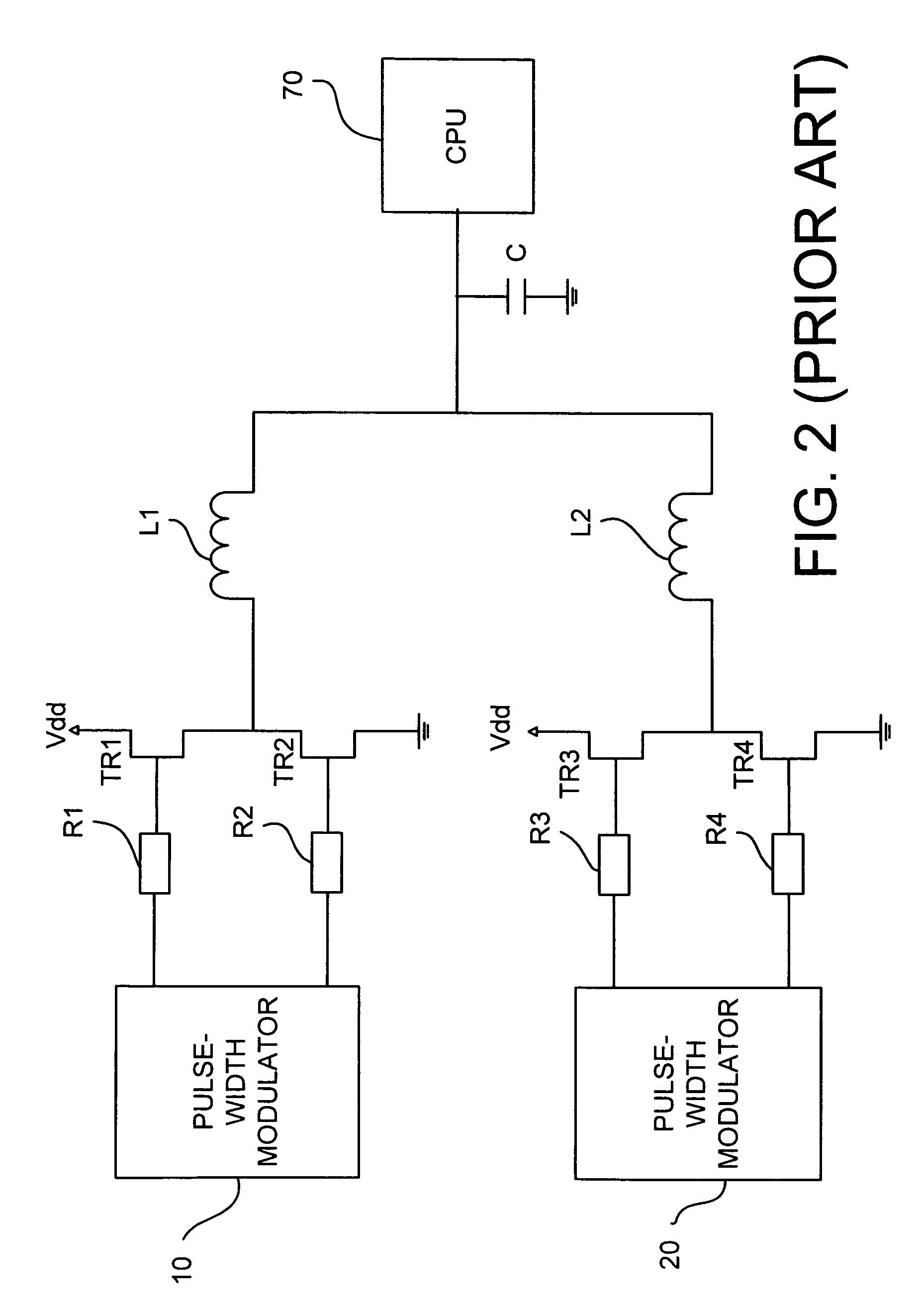
There is a limitation in the operation of the power converter of FIG. 2.
As described above in FIG. 1 and FIG. 2, for controlling multiple power converters of prior arts, additional pulse-width modulators and current-balancing circuits are required, and the costs are increased accordingly.

Method used


Image

  • Synchronized parallel running power converter
  • Synchronized parallel running power converter
  • Synchronized parallel running power converter

Examples


first embodiment

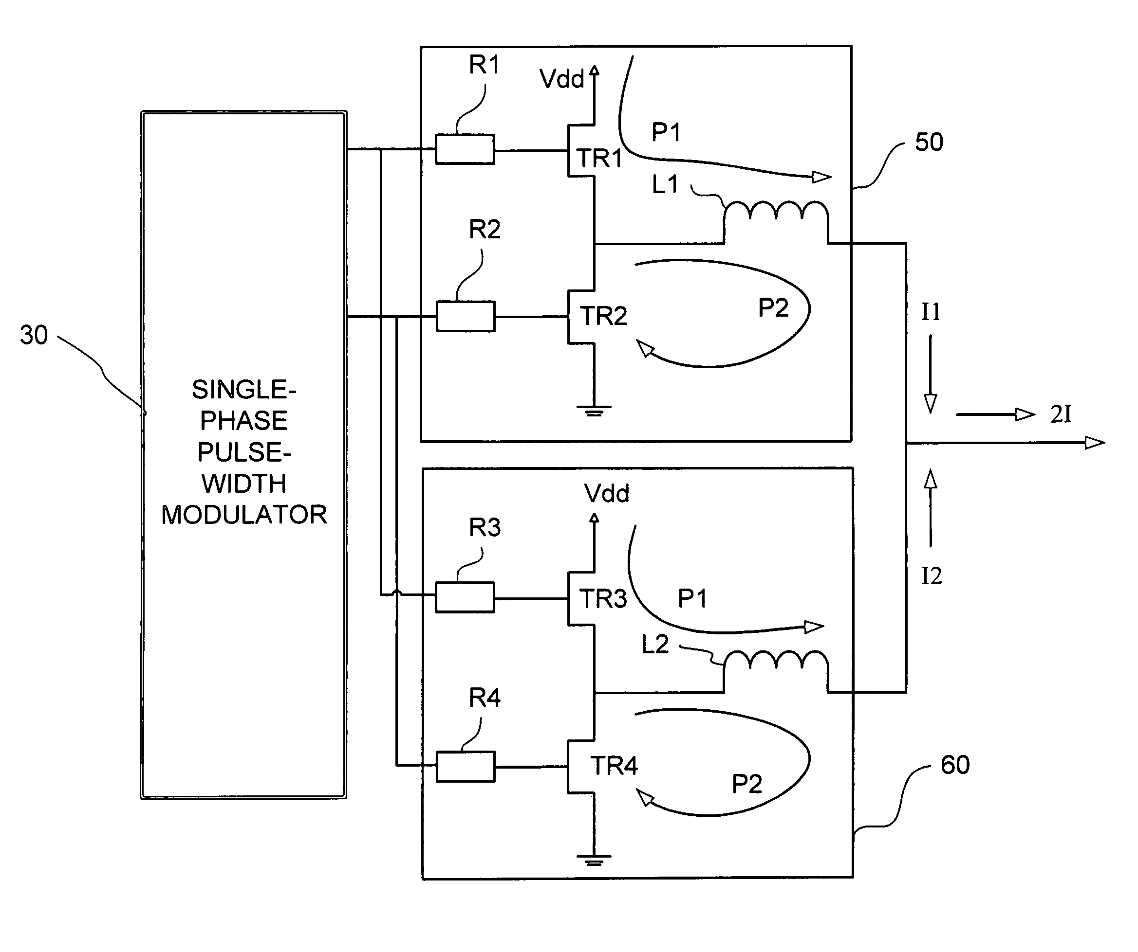
[0018]As shown in FIG. 3, the invention, a synchronized parallel running power converter includes a first power converter 50 and a second power converter 60 controlled by a single-phase pulse-width modulator 30. The single-phase pulse-width modulator 30 has a first pulse output port and a second pulse output port for pulse outputs. The first power converter 50 includes a first pulse input port, a second pulse input port and a current output port. The first pulse input port is coupled to the first pulse output port of the single-phase pulse-width modulator 30. The second pulse input port is coupled to the second pulse output port of the single-phase pulse-width modulator 30.

[0019]The first power converter 50 at least includes a first transistor TR1, a second transistor TR2 and a first inductor L1. The drain terminal of the first transistor TR1 is connected to the power source Vdd. The source terminal of the first transistor TR1 is connected to the drain terminal of the second transis...

second embodiment

[0026]As shown in FIG. 4, the invention, a synchronized parallel running power converter includes four power converters 50, 60, 80 and 90 and a double-phase pulse-width modulator 40. The double-phase pulse-width modulator 40 has a first pulse output port, a second pulse output port, a third pulse output port and a fourth pulse output port for pulse outputs. The first power converter 50 includes a first pulse input port, a second pulse input port and a current output port. The first pulse input port is coupled to the first pulse output port of the double-phase pulse-width modulator 40. The second pulse input port is coupled to the second pulse output port of the double-phase pulse-width modulator 40. The second power converter 60 includes a first pulse input port, a second pulse input port and a current output port. The first pulse input port is coupled to the first pulse output port of the double-phase pulse-width modulator 40. The second pulse input port is coupled to the second pu...


PUM


Abstract

In prior arts, additional pulse-width modulators and more costs are needed for increasing the current output. The invention provides a synchronized parallel running power converter. The power converter includes multiple power converters controlled by single-phase or double-phase pulse-width modulators. Each power converter includes a first pulse input port, a second pulse input port and a current output port. Each first pulse input ports are coupled, and each second pulse input ports are coupled also, so that each power converter is controlled by the same pulse signal and provide a same output current to be added as several times of current output.

Description

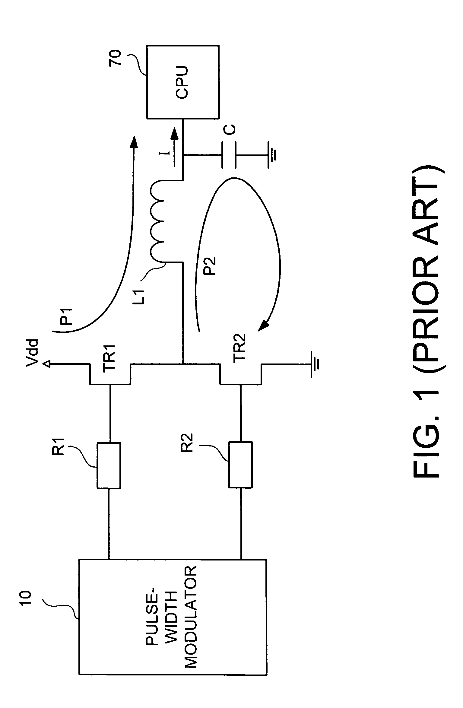
[0001]This Non-provisional application claims priority under 35 U.S.C. § 119(a) on Patent Application No. 092124503 filed in Taiwan on Sep. 4, 2003, the entire contents of which are hereby incorporated by reference.BACKGROUND OF THE INVENTION[0002]1. Field of the Invention[0003]The invention generally relates to a power converter, and in particular relates to multiple power converters running in parallel and synchronously.[0004]2. Related Art[0005]In conventional power converters, parallel circuits are used to increase the current output while preventing from power loss and heat generation caused by current increasing on each circuit.[0006]As shown in FIG. 1, a power converter of prior arts includes a pulse-width modulator 10, a first transistor TR1, a second transistor TR2 and an inductor L1. The drain terminal of the first transistor TR1 is connected to the power source Vdd. The source terminal of the first transistor TR1 is connected to the drain terminal of the second transistor...

Claims


Application Information

Patent Timeline
Patent Type & Authority Patents(United States)
IPC IPC(8): G05F1/59H02M3/158
CPCH02M3/1584
Inventor HSU, CHIEN-CHIHSIEH, WEN-CHICHENG, FU-KANG
Owner MICRO-STAR INTERNATIONAL
Learn More