Optical mouse with rolling ball

a mouse and optical technology, applied in the field of optical mouse, can solve the problems of inconvenient user, degraded performance of mechanical mouse, bulky and heavy steel ball, etc., and achieve the effect of low cost and high light transmission efficiency

Inactive Publication Date: 2006-07-04
EDISON-OPTO
View PDF12 Cites 30 Cited by
  • Summary
  • Abstract
  • Description
  • Claims
  • Application Information

AI Technical Summary

Benefits of technology

[0007]It is an object of the present invention to provide an o...

Problems solved by technology

However, the performance of the mechanical mouse is degraded after a long time use due to ball abrasion and dust inleakage.
Moreover, the mechanical mouse uses a bulky and heavy steel ball, which is also inconvenient for use...

Method used


Image

  • Optical mouse with rolling ball
  • Optical mouse with rolling ball
  • Optical mouse with rolling ball

Examples


Embodiment Construction

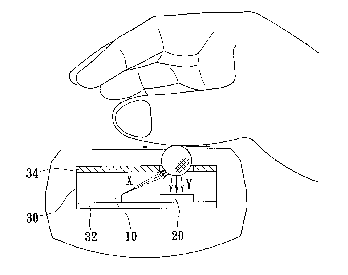
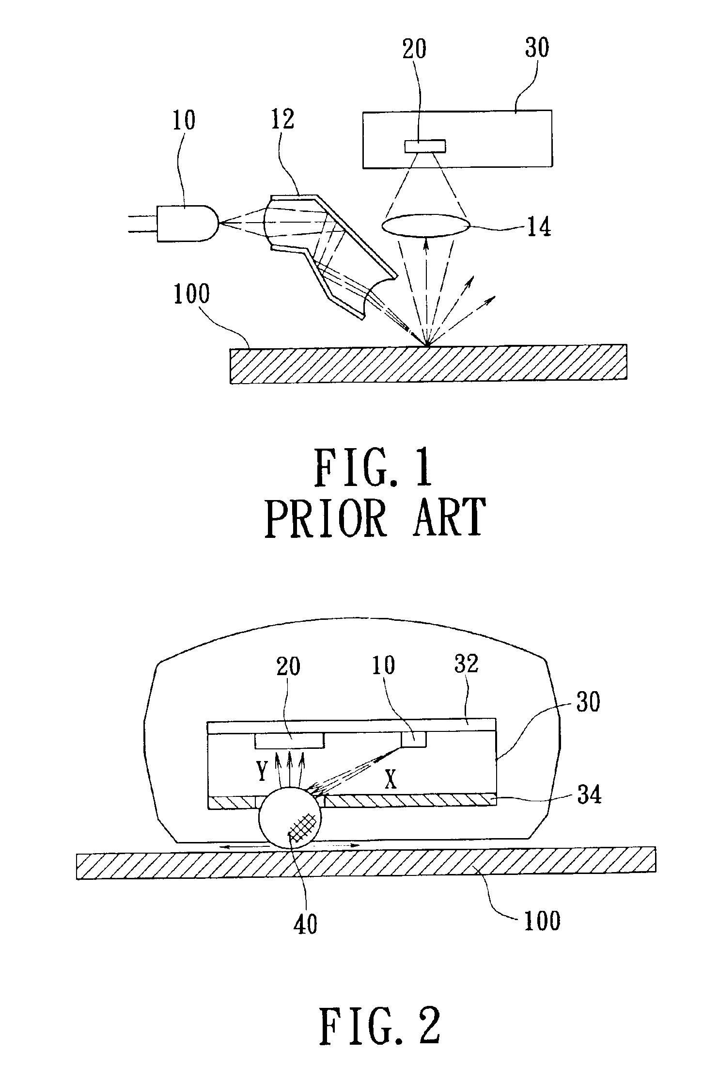
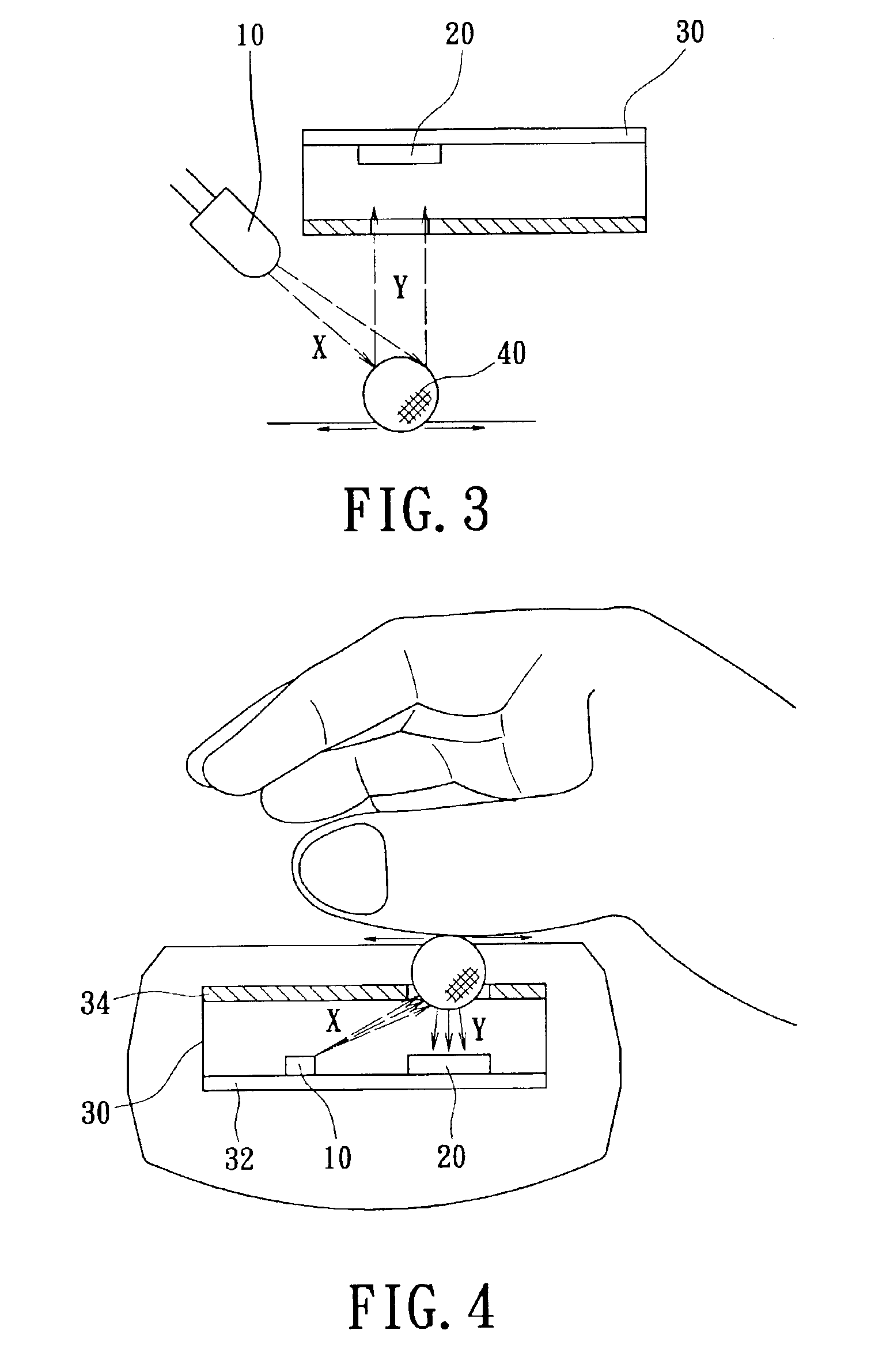
[0020]FIG. 2 shows a sectional view of an optical mouse 1 according to the first preferred embodiment of the present invention. The optical mouse 1 according to this preferred embodiment of the present invention comprises at least a light transmitter 10 such as LED for emitting a light beam, a casing 30, a light receiver 20 (such as CMOS sensor array or a CCD array) arranged on a first face 32 of the casing 30, and a rolling ball 40 mounted within a rounded hole (not labeled) on a second face 34 of the casing 30 opposite to the first face 32. The rolling ball 40 has size of 1-10 mm. When the mouse is moved, the light beam is reflected by the rolling ball 40 rolled along a work surface and an image of the rolling ball 40 is detected by the light receiver 20. In this preferred embodiment of the present invention, the light beam is subjected to only one reflection by the ball 40, the transmission efficiency is enhanced. Therefore, a low-power light source is feasible and the cost can b...


PUM


Abstract

An optical mouse is operated on a work surface and includes at least one light emitter for emitting a light beam; a light receiver contained by a casing; a rolling ball arranged on the casing and opposite to the light receiver. The light beam has only one reflection by the rolling ball during an optical path thereof and then is detected by the light receiver. The rolling ball is made of transparent material and the distance thereof with the light receiver is adjustable to vary image resolution. The optical mouse can be turned over and placed on a notebook computer for using as a track ball.

Description

FIELD OF THE INVENTION[0001]The present invention relates to an optical mouse, especially to an optical mouse with rolling ball.BACKGROUND OF THE INVENTION[0002]In personal computer, the computer mice are popular pointing means for input data and cursor control. A conventional mechanical mouse generally employs a rolling ball and at least two encoder wheels for x- and y-axis. The encoder wheels are driven by the roll ball when a user moves the mouse along a flat surface such as a mouse pad. The encoder wheels will intermittently block a light propagation in the mouse and associated electronic signal is generated to control cursor movement on a computer display. However, the performance of the mechanical mouse is degraded after a long time use due to ball abrasion and dust inleakage. Moreover, the mechanical mouse uses a bulky and heavy steel ball, which is also inconvenient for user.[0003]To overcome those drawbacks, an optical mouse is provided and has a light transmitter such as l...

Claims


Application Information

Patent Timeline
IPC IPC(8): G09G5/08G06F3/03
CPCG06F3/0312G06F3/0383G06F3/0317
Inventor SUN, TSUNG-TINGCHUANG, JUI-CHIENTSAI, CHENG-HUNGHUANG, HSUAN KAI
Owner EDISON-OPTO
Why Eureka
Try Eureka