Flexible nerve photoelectrode for nerve recording and stimulation and preparation method thereof

A technology of photoelectrodes and laser diodes, which is applied to lasers, laser components, semiconductor lasers, etc., can solve problems such as stimulation and the inability to adjust the position of flexible LED electrodes, and achieve the effects of reducing electromagnetic interference, reducing brain tissue damage, and good flexibility

Active Publication Date: 2020-09-01
杭州电子科技大学温州研究院有限公司 +1
View PDF5 Cites 6 Cited by
  • Summary
  • Abstract
  • Description
  • Claims
  • Application Information

AI Technical Summary

Problems solved by technology

However, there are still some deficiencies in the above three flexible photoelectrode structures. For example, the flexible optical fiber needs to be manually integrated with the wire electrode, the flexible Parylene electrode is mainly used for light stimulation on the cortical surface, and the flexible LED electrode cannot be adjusted after injection.

Method used


Image

  • Flexible nerve photoelectrode for nerve recording and stimulation and preparation method thereof
  • Flexible nerve photoelectrode for nerve recording and stimulation and preparation method thereof
  • Flexible nerve photoelectrode for nerve recording and stimulation and preparation method thereof

Examples


Embodiment 1

[0060] The specific steps of the preparation method of the flexible neural photoelectrode for nerve recording and stimulation are as follows:

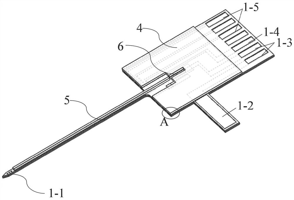
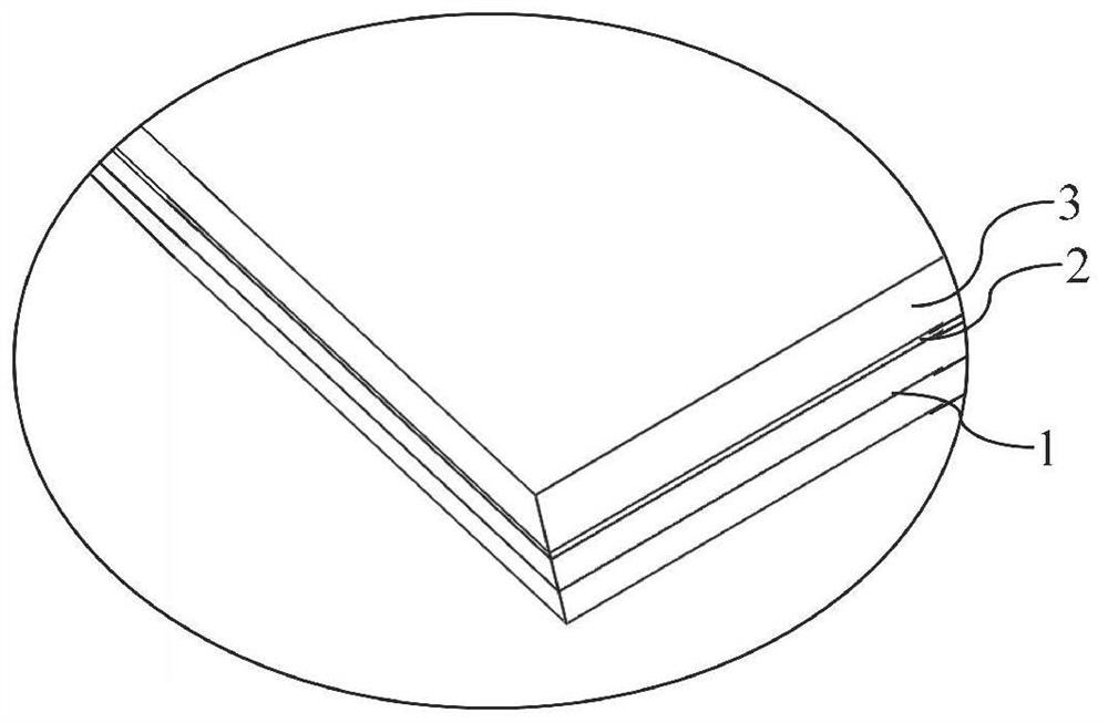
[0061] S1: Using ultra-thin PI as the recording electrode insulating layer, and integrating SU-8 optical waveguide on the insulating layer to realize photostimulation. In the conductive layer in the insulating layer, the power supply wire of the laser diode 6 is surrounded by a ground wire and a metal shielding layer, and the electromagnetic interference of the laser diode 6 to the recording channel is reduced by electromagnetic shielding.

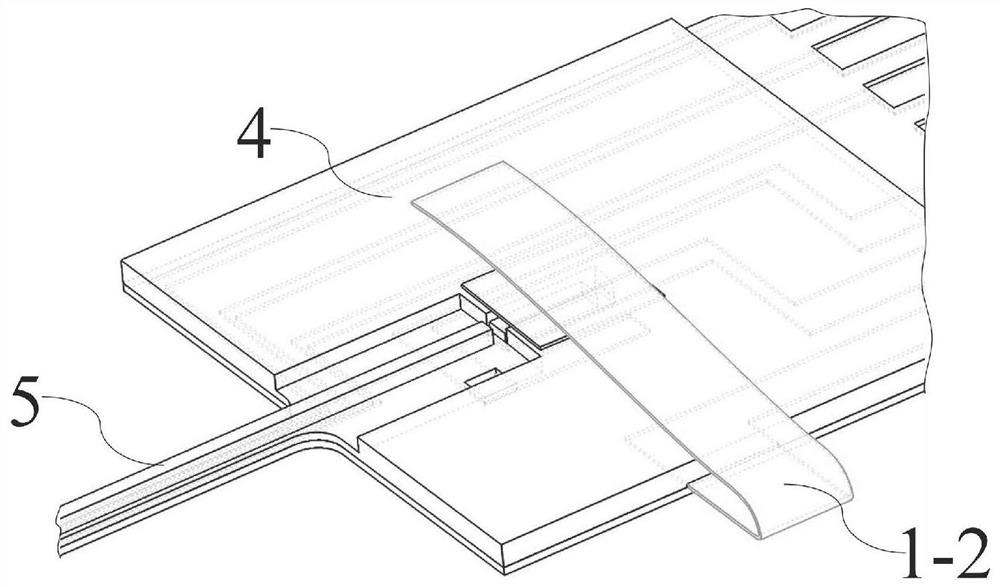
[0062] S2: use the LD placement groove to realize the alignment of the laser diode 6 and the optical waveguide structure on the probe, and realize the thermocompression bonding between the LD placement groove and the LD bonding pad 1-2 through the ACF conductive glue.

[0063] The specific process of step S1 is as follows:

[0064] Use ordinary single-sided polished silicon wafers as the substrate...

Embodiment 2

[0092] Preparation of flexible neural photoelectrode: Same as Example 1.

[0093] Electromagnetic shielding layer design: same as embodiment 1.

[0094] Flexible neural photoelectrode integrated with LD:

[0095] In the first step, use a dispenser to apply conductive silver paste on the pad in the LD placement groove. As an alternative, a steel needle can also be used to replace the dispenser to manually apply conductive silver paste in the groove. Pay attention to the amount of conductive silver paste used during the coating process to avoid blocking the light outlet of the laser diode 6 or connecting the upper and lower pads of the laser diode 6 in series due to the overflow of the conductive silver paste.

[0096] In the second step, use a wire bonding machine to put the cathode pad of laser diode 6 down into the LD placement groove and align it with the optical waveguide structure on the probe

[0097] . The specific steps are as follows: place the glass slide containi...


PUM

PropertyMeasurementUnit
thicknessaaaaaaaaaa
thicknessaaaaaaaaaa
thicknessaaaaaaaaaa

Abstract

The invention discloses a flexible nerve photoelectrode for nerve recording and stimulation and a preparation method of the flexible nerve photoelectrode. An existing nerve electrode can only collectsignals, cannot stimulate the brain, and is often too rigid or too soft, thereby result in difficult brain injury or implantation. The flexible nerve photoelectrode for nerve recording and stimulationdisclosed by the invention comprises a recording layer, an electromagnetic shielding layer and a photostimulation layer, wherein the recording layer, the electromagnetic shielding layer and the photostimulation layer which are sequentially stacked together form a neural photoelectrode structure; the tip of a probe is provided with an exposed recording electrode point; the photostimulation layer on the probe forms an optical waveguide structure with a rectangular cross section; an LD placement groove is formed in the photostimulation layer on an electrode base body; a stimulation light sourceis arranged in the LD placement groove; and the stimulation light source is aligned with an optical waveguide structure on the probe. The flexible nerve photoelectrode has good flexibility, the SU-8 photoresist provides proper rigidity, and bending of the electrode probe during implantation is avoided while the light transmission efficiency is improved.

Description

technical field [0001] The present invention relates to the preparation of flexible biosensors in the field of brain-computer interface, in particular, to a micro-processing preparation method of flexible neural photoelectrodes for neural recording and stimulation, which is achieved by coupling ultra-thin flexible recording electrodes with LD SU-8 The optical waveguide structure is prepared by optoelectronic integration. Background technique [0002] In the past few years, the rapid development of microelectromechanical system technology and optoelectronic technology has made the electrophysiological recording and photostimulation performance of silicon-based neural photoelectrodes unprecedentedly improved. On the one hand, the advanced electron beam exposure technology has greatly improved the spatial resolution of recording electrode points; on the other hand, by integrating optical waveguides, laser diodes6 and micro LEDs, etc., the stimulation spatial resolution of silic...

Claims


Application Information

Patent Timeline
Patent Type & Authority Applications(China)
IPC IPC(8): H01S5/022A61B5/0478A61B5/0484
CPCA61B2562/16A61B2562/164A61B2562/182
Inventor 王明浩郭帮帮程瑜华杨文伟陈颖叶柳顺王高峰
Owner 杭州电子科技大学温州研究院有限公司
Why Eureka
Try Eureka