Photonic crystal waveguide TM-polarization separator

A photonic crystal waveguide, polarization splitter technology, applied in the coupling of optical waveguides, light guides, instruments, etc., to achieve the effects of high optical transmission efficiency, high degree of polarization, and easy integration

Inactive Publication Date: 2012-08-29
SHENZHEN UNIV
View PDF4 Cites 7 Cited by
  • Summary
  • Abstract
  • Description
  • Claims
  • Application Information

AI Technical Summary

Problems solved by technology

The polarization splitter obtained by these two methods, although its volume is much smaller than the traditional polarization splitter, still appears relatively large.

Method used


Image

  • Photonic crystal waveguide TM-polarization separator
  • Photonic crystal waveguide TM-polarization separator
  • Photonic crystal waveguide TM-polarization separator

Examples


Embodiment Construction

[0023] The present invention will be further described below in conjunction with the accompanying drawings.

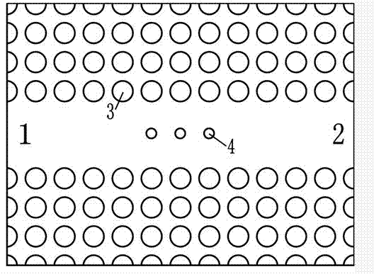
[0024] The dielectric material in the introduction of the principle of the present invention and in the specific implementation mode is all taken as an example of a tellurium dielectric column. First build a positive uniaxial crystal tellurium array arranged in a square lattice on the substrate, and then delete two rows or two columns at the center to form a waveguide, and both TE and TM light propagate in the form of fundamental mode. Background The direction of the e-ray optical axis of each dielectric pillar in the tellurium dielectric pillar array must be consistent with the axis direction of the cylinder. The working wavelength can be adjusted by the lattice constant between the dielectric columns, but the selection of the working wavelength cannot exceed the linear stable range of the refractive index.

[0025] Such as figure 1 As shown, the tellurium diel...


PUM


Abstract

The invention discloses a photonic crystal waveguide TM-polarization separator comprising a photonic crystal waveguide with a complete forbidden band. The incident waves in any polarization direction of the input end of the photonic crystal waveguide are incident into the polarization separator, TM waves are output from the output end of the polarization separator, and TE waves return by reflection from the input end of the polarization separator. According to the photonic crystal waveguide TM-polarization separator, the structure size is small, the degree of polarization is high, the light transmission efficiency is high, the integration is convenient and the efficiency is high, and the photonic crystal waveguide TM-polarization separator is suitable for large-scale optical path integration and can realize the functions of the polarization beam splitting of different wavelengths.

Description

technical field [0001] The invention relates to the field of tiny optical polarization splitters, in particular to a tiny optical polarization splitter based on photonic crystal technology. Background technique [0002] Traditional polarization splitters are bulky and cannot be used in optical path integration. Microscopic devices, including polarization splitters, can be fabricated on the basis of photonic crystals. There are currently two methods: one is to use a photonic crystal with TE forbidden band and TM conduction band or TM forbidden band and TE conduction band to realize the polarization separation of waves. This kind of polarization splitter can only be used as a single photonic crystal device in traditional optical waveguides due to its poor transmittance and polarization degree, and it is difficult to integrate into other photonic crystal devices. The other is to couple light waves with different polarization states to different waveguides by designing...

Claims


Application Information

Patent Timeline
Patent Type & Authority Applications(China)
IPC IPC(8): G02B6/27G02B6/126G02B6/122
CPCG02B1/005B82Y20/00G02B6/1225G02B6/126G02B27/283
Inventor 欧阳征标金鑫
Owner SHENZHEN UNIV
Why Eureka
Try Eureka