
Digital camera having automatic exposure control for different photographing modes

Inactive Publication Date: 2006-07-04
MINOLTA CO LTD
View PDF13 Cites 38 Cited by
  • Summary
  • Abstract
  • Description
  • Claims
  • Application Information

AI Technical Summary

Benefits of technology

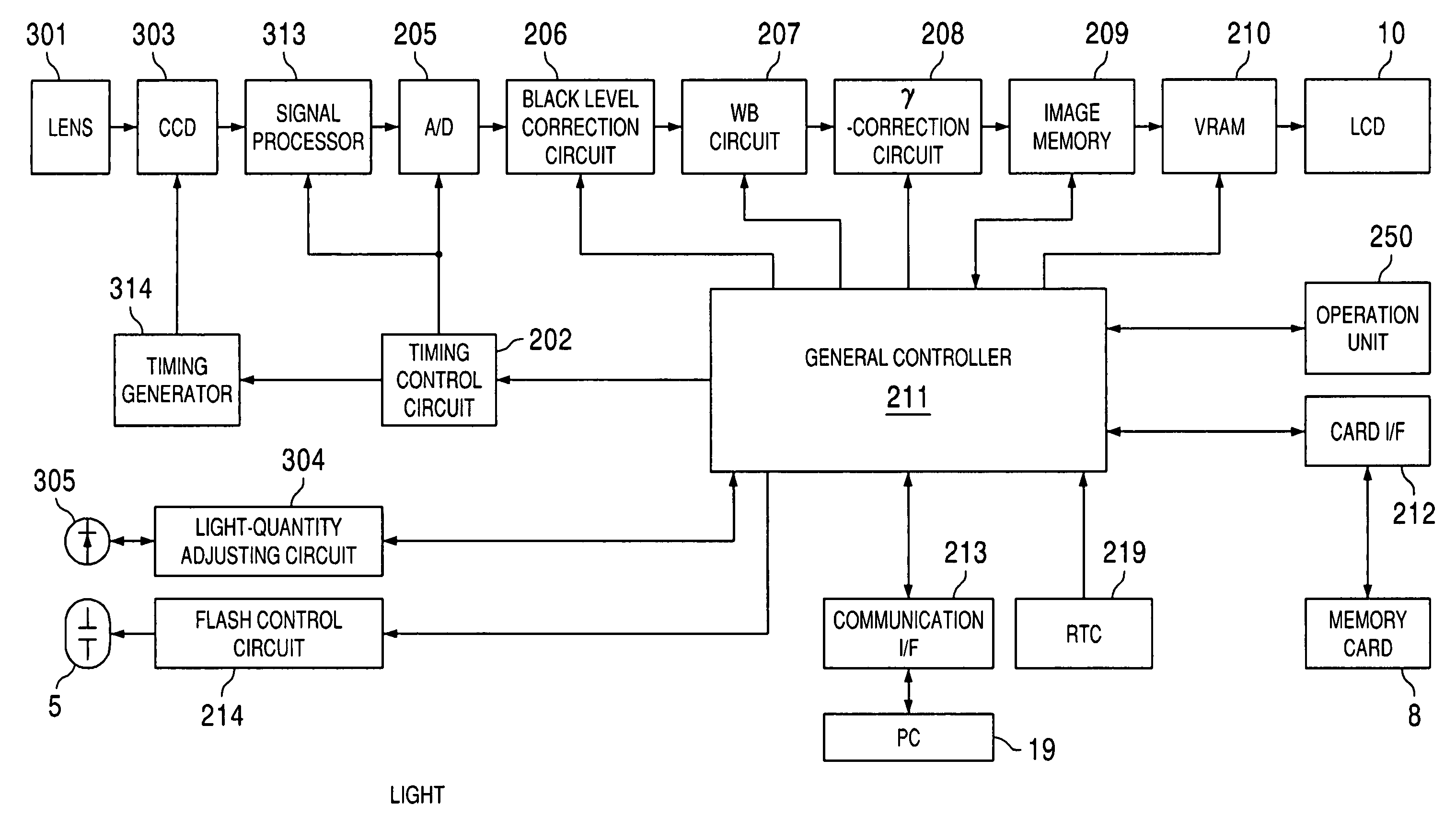
[0010]Therefore, it is an object of the invention to provide a digital camera which can follow a change in the brightness of the object even in the high-speed sequence-photograph mode so that a high-quality image with an appropriate exposure can be obtained.
[0011]It is another object of the present invention to provide a digital camera which does not require a light-receiving element exclusively used for exposure control, and can reduce the size and the manufacturing cost.
[0015]On the other hand, in the execution of the sequence photograph mode, the exposure amount of the image pick-up element is controlled based on the output of the light-receiving element. Accordingly, during a high-speed successive photographing operation, any changes in the brightness of the object can be promptly reflected in the exposure amount for the next shot (or frame). Unlike the conventional digital camera which calculated the exposure amount from the image data output from the CCD array for each photographing action, the digital camera of the present invention can provide the optimal exposure amount for each shot even in the high-speed sequence photograph mode.

Problems solved by technology

If a priority is given to the high-speed successive photographing without adjusting the exposure value the quality of the resultant images is deteriorated due to inappropriate exposure because the photographing conditions cannot follow the change in the brightness of the object.
However, because the exclusive light-receiving device is required other than the CCD, the number of components increases, the size of the camera becomes larger and the cost of manufacturing the digital camera also increases.

Method used


Image

  • Digital camera having automatic exposure control for different photographing modes
  • Digital camera having automatic exposure control for different photographing modes
  • Digital camera having automatic exposure control for different photographing modes

Examples


Embodiment Construction

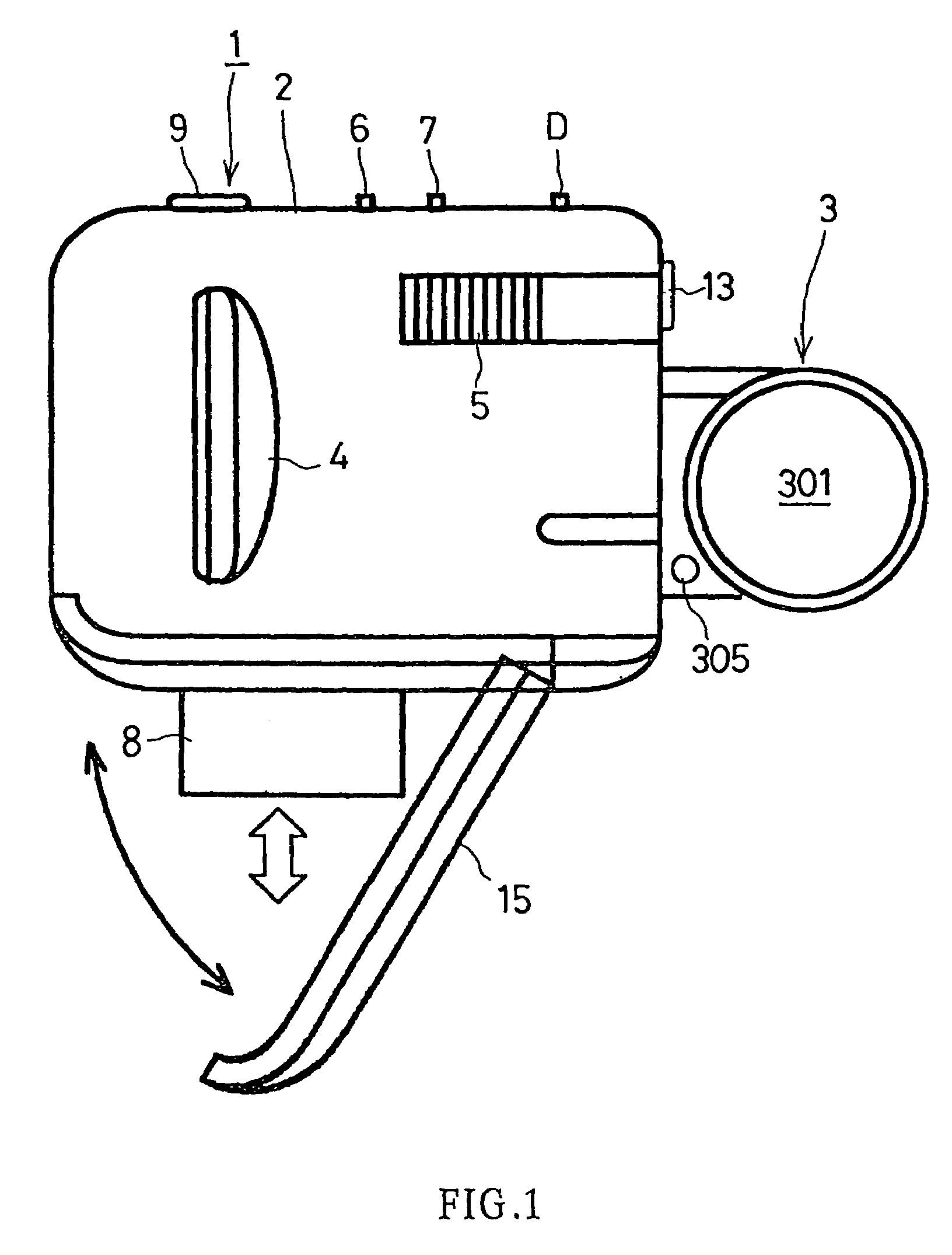
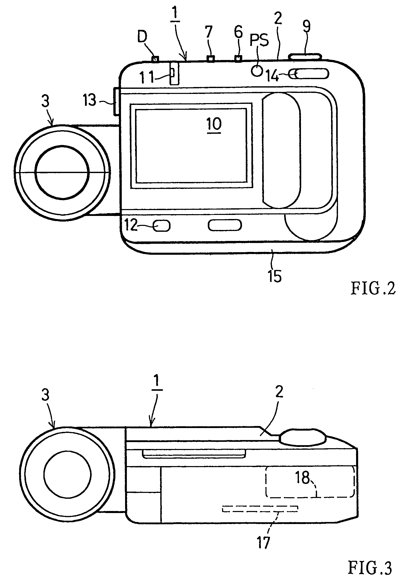
[0024]As shown in FIGS. 1–3, a digital camera 1 comprises a camera frame, which is referred to as a main body 2, and a photographing unit 3 which is attachable to and removable from the main body 2 on the right side of the main body 2 in the front view shown in FIG. 1. The photographing unit 3 is pivotable within a plane parallel to the right side of the main body 2.

[0025]The photographing unit 3 has a photographing device comprising a macrozoom lens 301 and a photoelectric conversion device such as a CCD (Charge Coupled Device) array, to convert the optical image of an object into an electric image consisting of charge signals, each of which was generated by each pixel of the CCD via photoelectric conversion. The main body 2 has a display or LCD (Liquid Crystal Display) 10, a slot 17 for receiving a memory card 8, and a connection terminal 13 for connecting the digital camera 1 to a personal computer. The image signal taken by the photographing unit 3 is subjected to a prescribed i...


PUM


Abstract

A digital camera includes an image pick-up element which receives light reflected from an object and generates image data of the object, and a light-receiving element which receives light reflected form the object and outputs light-quantity data for the object. The light-receiving element differs from the image pick-up element. In the sequence photograph mode, the exposure amount of the image pick-up element is controlled based on the light-quantity data output from the light-receiving element. In the other modes, the exposure amount of the image pick-up element is controlled based on the image data generated by the image pick-up element itself.

Description

[0001]The present invention claims a priority based on the Japanese Patent Application No. H10-209697, the contents of which is incorporated hereinto by reference in its entirety.BACKGROUND OF THE INVENTION[0002]1. Field of the Invention[0003]This invention relates to a digital camera and a method for controlling the exposure of the digital camera.[0004]2. Description of the Related Art[0005]As it is known, the photographing lens of a digital camera focuses an optical image onto a CCD (charge coupled device), which then photoelectrically converts the optical image into an electric signal. The generated electric signal is subjected to predetermined image processing, so that the photographed image is recorded as digital image data in a recording medium, such as a memory card. The recorded digital image is displayed on a display (e.g., an LCD panel).[0006]A typical digital camera also has an exposure control system. A conventional exposure control system for a digital camera computes a...

Claims


Application Information

Patent Timeline
IPC IPC(8): H04N5/235G03B7/00H04N5/225H04N5/765H04N5/335H04N5/351H04N5/353H04N5/357H04N5/363H04N5/372H04N5/378H04N5/77H04N5/781H04N5/907H04N5/91H04N9/804H04N9/82
CPCH04N5/23245H04N5/2351H04N5/2354H04N5/772H04N5/765H04N9/8227H04N5/907H04N9/8042H04N9/8205H04N23/667H04N23/71H04N23/74
Inventor TANAKA, TOSHIYUKI
Owner MINOLTA CO LTD
Learn More