

Image synthesis apparatus
a technology of image synthesis and apparatus, applied in the field of image synthesis apparatus, can solve the problems of inability to quickly and accurately grasp the state of the site, inability to obtain sufficient information for diagnosis, and inability to quickly and accurately diagnose. , to achieve the effect of rapid and accurate grasping and rapid and accurate diagnosis
- Summary
- Abstract
- Description
- Claims
- Application Information
AI Technical Summary
Benefits of technology
Problems solved by technology
Method used
Image

Examples
example 1
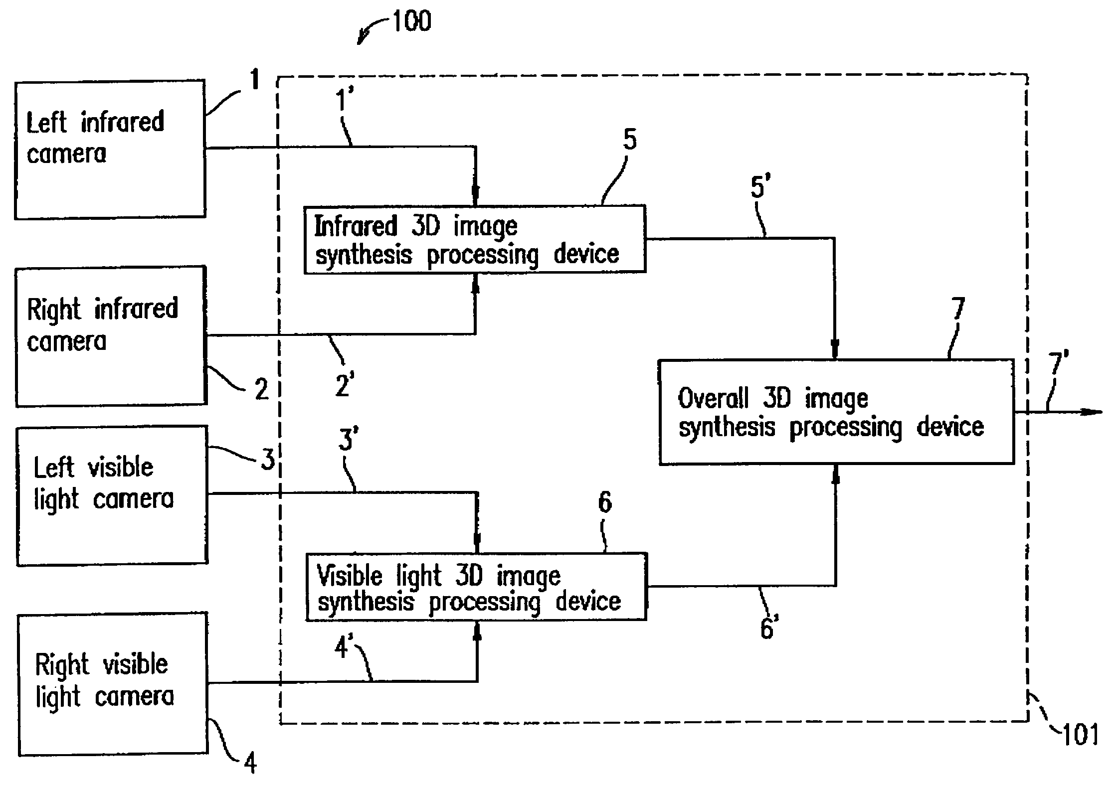
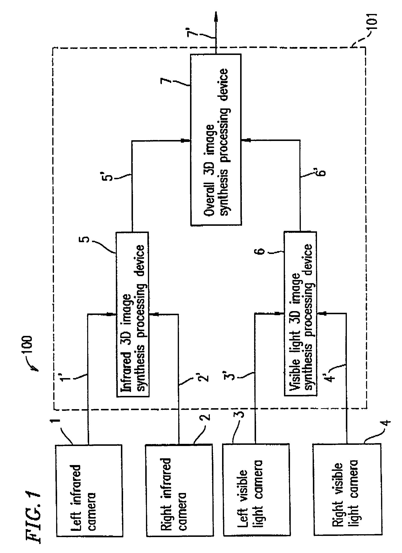
[0031]FIG. 1 shows a structure of an image synthesis apparatus 100 according to a first example of the present invention. The image synthesis apparatus 100 is used for, for example, diagnosing an inflammation site of a human body as a subject of imaging.
[0032]The image synthesis apparatus 100 includes a left infrared camera 1, a right infrared camera 2, a left visible light camera 3, a right visible light camera 4, and an image synthesis processing device 101. The image synthesis processing device 101 includes an infrared 3D image synthesis processing device 5, a visible light 3D image synthesis processing device 6, and an overall 3D image synthesis processing device 7.
[0033]The left infrared camera 1 and the right infrared camera 2 respectively image a subject (not shown) from a left position corresponding to a left eye and a right position corresponding to a right eye, and thus generate infrared image data. The left visible light camera 3 and the right visible light camera 4 respe...
example 2
[0052]FIG. 4 shows a structure of an image synthesis apparatus 200 according to a second example of the present invention.
[0053]The image synthesis apparatus 200 includes a right infrared camera 201, a right visible light camera 202, a left infrared camera 203, a left visible light camera 204, an image synthesis processing device 215, and a monitor 209. The image synthesis processing device 215 includes a right image synthesis processing device 205, a left image synthesis processing device 206, a synchronous signal generator 207, and a data output device 208.
[0054]The right infrared camera 201 and the left infrared camera 203 respectively image a subject 213 from a right position corresponding to a right eye and a left position corresponding to a left eye, and thus generate right infrared image data 221 and left infrared image data 223. The right visible light camera 202 and the left visible light camera 204 respectively image the subject 213 from a right position corresponding to a...
example 3
[0073]FIG. 8 shows a structure of an image synthesis apparatus 300 according to a third example of the present invention.
[0074]The image synthesis apparatus 300 includes an image synthesis processing section 215′, a monitor 309, and a polarizer 310 in addition to the right infrared camera 201, the right visible light camera 202, the left infrared camera 203, and the left visible light camera 204. The image synthesis processing section 215′ includes a right image synthesis processing section 205, a left image synthesis processing section 206, a synchronous signal generator 207, and a data output device 218 for outputting overall synthesis image data 227′ to the monitor 309. The overall synthesis image data 227′ has the same data structure as that of the overall synthesis image data 227 shown in FIG. 5C, except that the overall synthesis image data 227′ includes instruction data for instructing the monitor 309 to display the right synthesis image data 225 and the left synthesis image ...
PUM
 Abstract
Description
Claims
Application Information