Image forming apparatus and image method for forming toner images with optimized patch image density

a technology of image forming apparatus and patch image density, which is applied in the direction of electrographic process apparatus, instruments, optics, etc., can solve problems such as detection errors, and achieve the effect of increasing the cost of the apparatus and simplifying the control

Inactive Publication Date: 2006-07-04
SEIKO EPSON CORP
View PDF21 Cites 30 Cited by
  • Summary
  • Abstract
  • Description
  • Claims
  • Application Information

AI Technical Summary

Benefits of technology

[0024]Furthermore, the control is simplified because the optimum value of one parameter can be determined based on the densities of the patch images formed with only the parameter in question varied. Hence, the present invention does not have a problem associated with increased costs of the apparatus due to the complicated control or time-consuming processes, as encountered by the conventional art.

Problems solved by technology

As mentioned supra, the toner densities of the patch images detected by the density detecting means may potentially include detection errors associated with the variations of the sensor characteristics and the like.
In general, such detection errors are encountered by individual patch images in a similar manner.

Method used


Image

  • Image forming apparatus and image method for forming toner images with optimized patch image density
  • Image forming apparatus and image method for forming toner images with optimized patch image density
  • Image forming apparatus and image method for forming toner images with optimized patch image density

Examples


first embodiment

(1) Arrangement of Apparatus

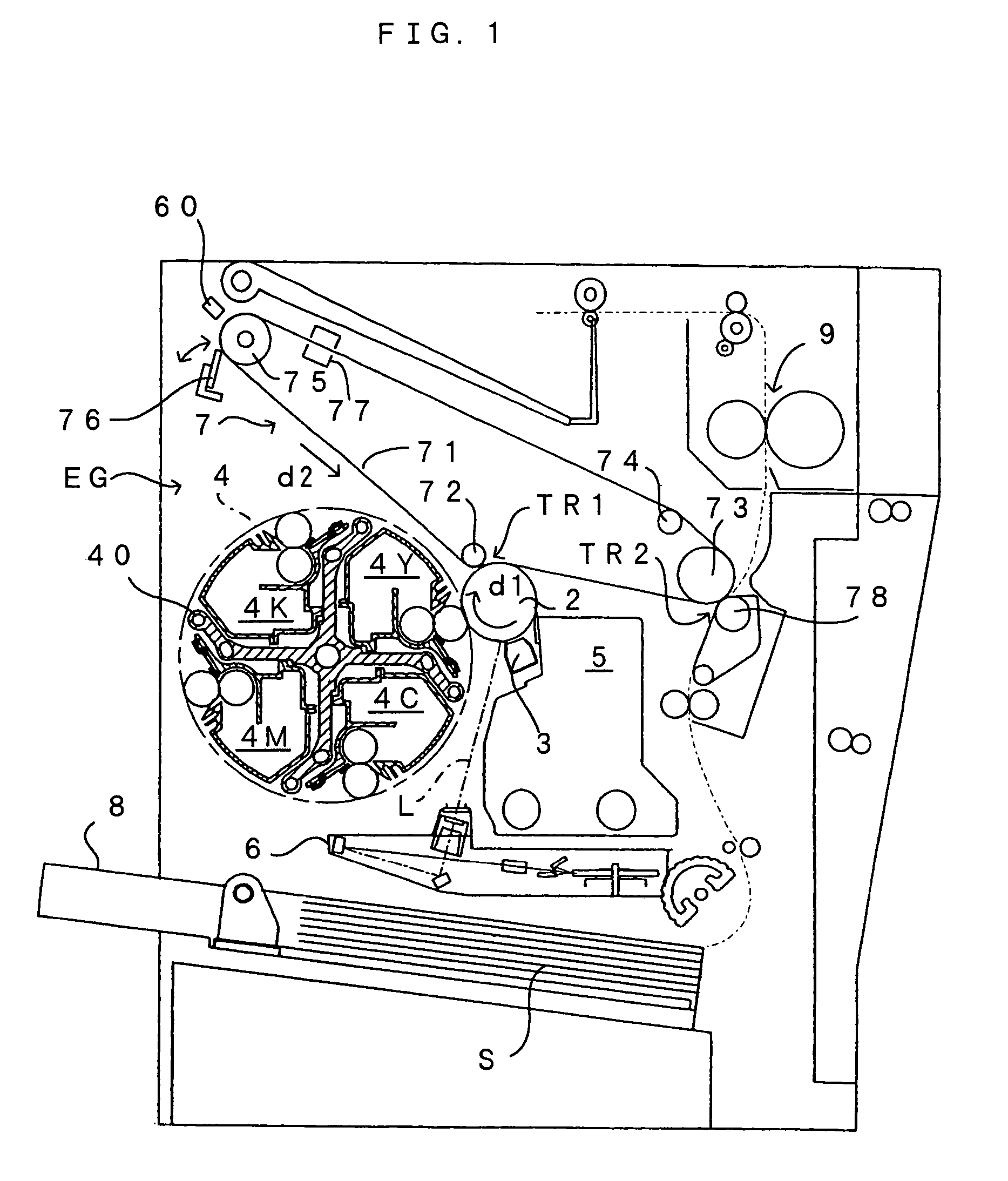
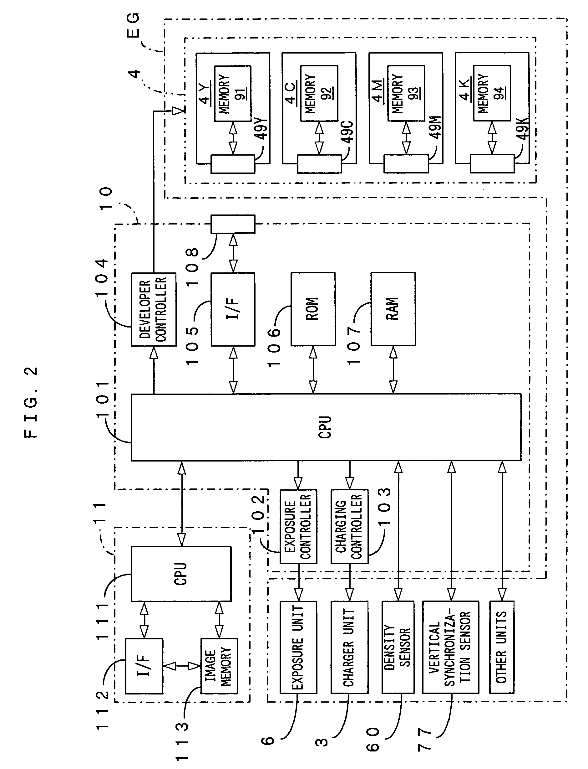
[0080]FIG. 1 is a diagram showing an image forming apparatus according to a first embodiment of the present invention, whereas FIG. 2 is a block diagram showing an electrical arrangement of the image forming apparatus of FIG. 1. The image forming apparatus is adapted to form a full-color image by superimposing toner images of four colors, including yellow (Y), cyan (C), magenta (M) and black (K), on one another or to form a monochromatic image using a black (K) toner alone. The image forming apparatus operates as follows. When an external apparatus such as a host computer supplies an image signal to a main controller 11 in response to a user demand for forming an image, an engine controller 10 functioning as “image forming means” of the present invention responds to the command from the main controller 11. The engine controller 10 controls individual portions of an engine EG whereby an image corresponding to the image signal is formed on a sheet S.

[0081]T...

second embodiment

[0216]FIG. 28 is a diagram showing a light-quantity control signal conversion section according to a second embodiment. In the apparatus of the first embodiment (FIG. 4), the CPU 101 outputs the light-quantity control signal Slc directly to the irradiation-light-quantity regulating unit 605 of the density sensor 60. In contrast, the apparatus of the second embodiment differs from that of the first embodiment in that a light-quantity control signal conversion section 200 is interposed between the CPU 101 and the irradiation-light-quantity regulating unit 605.

[0217]The light-quantity control signal conversion section 200 operates to supply a light-quantity control signal Slc to the irradiation-light-quantity regulating unit 605 of the density sensor 60, the light-quantity control signal Slc having a voltage value based on two types of digital signals DA1 and DA2 outputted from the CPU 101 for light quantity control. The light-quantity control signal conversion section 200 includes two...

third embodiment

[0243]Next, description is made on an image forming apparatus according to a third embodiment of the present invention. The image forming apparatus of this embodiment is constructed by adding the light-quantity control signal conversion section 200 of the second embodiment to the image forming apparatus of the first embodiment described above. As will be described hereinlater, however, the arrangement of the apparatus is partially varied and hence, a part of the optimization process for density control factor is also changed. Of the arrangement of the apparatus and the optimization process for density control factor, the description is made on differences from the foregoing first and second embodiments on an item-by-item basis and the explanation on the common features to these embodiments is dispensed with.

(1) Difference in the Apparatus Arrangement

[0244]According to the description of the first embodiment described above, the density sensor 60 (FIG. 4) is constructed such that the...


PUM


Abstract

In a density control technique wherein a density of a toner image formed as a patch image is detected for performing density control based on the detected result, detection errors are decreased so as to properly set a density control factor. The density control factor is optimized based on a variation rate of the patch image densities against a varied density control factor. The detected results of the patch image densities are corrected based on information on an image carrier acquired before the formation of the patch images.

Description

TECHNICAL FIELD[0001]The present invention relates to a technique for stabilizing an image density in electrophotographic image forming apparatuses such as printers, copy machines and facsimile machines.BACKGROUND ART[0002]The image forming apparatuses, such as copy machines, printers and facsimile machines, applying the electrophotographic techniques may encounter image density variations of a toner image due to individually different characters of apparatuses, variations with time, or changes of conditions surrounding the apparatus which include temperature, moisture and the like. Heretofore, there have been proposed a variety of techniques for ensuring a stable image density, which include, for example, a technique wherein a small test image (patch image) is formed on an image carrier such that a density control factor affecting the image density may be optimized based on the density of the patch image. This technique takes the following approach to attain a desired image density...

Claims


Application Information

Patent Timeline
Patent Type & Authority Patents(United States)
IPC IPC(8): G03G15/00G03G15/08
CPCG03G15/0855G03G15/5058G03G15/0863G03G15/5041G03G2215/00042G03G2215/00059
Inventor SHIMURA, HIDETSUGUHAMA, TAKASHINAKASHIMA, YOSHIHIRO
Owner SEIKO EPSON CORP
Why Eureka
Try Eureka