
Digital trigger filter for a real time digital oscilloscope

a digital oscilloscope and trigger filter technology, applied in the direction of digital computer details, noise figure or signal-to-noise ratio measurement, instruments, etc., can solve the problems of high cost, easy failure, complicated, etc., and achieve the effect of aggressive suppression of high frequencies

Active Publication Date: 2006-07-04
KEYSIGHT TECH
View PDF24 Cites 48 Cited by
  • Summary
  • Abstract
  • Description
  • Claims
  • Application Information

AI Technical Summary

Benefits of technology

The patent describes a real-time digital signal processing system that includes a digital trigger filter with the ability to reject high and low frequencies, as well as produce an AC and DC trigger signal. The system uses a combination of digital filters and a conditioned input signal to achieve efficient and effective triggering. The technical effect of this invention is to provide a more precise and versatile trigger filter for digital signal processing.

Problems solved by technology

It is made more complicated when the signal being observed contains many different components, or types of behaviors.
They are implemented with actual physical circuitry, and as such are limited in their range of operation by the dictates of circuit design and its compromises, they take space and generate heat, require adjustment, are susceptible of failure, and they cost money.

Method used


Image

  • Digital trigger filter for a real time digital oscilloscope
  • Digital trigger filter for a real time digital oscilloscope
  • Digital trigger filter for a real time digital oscilloscope

Examples


Embodiment Construction

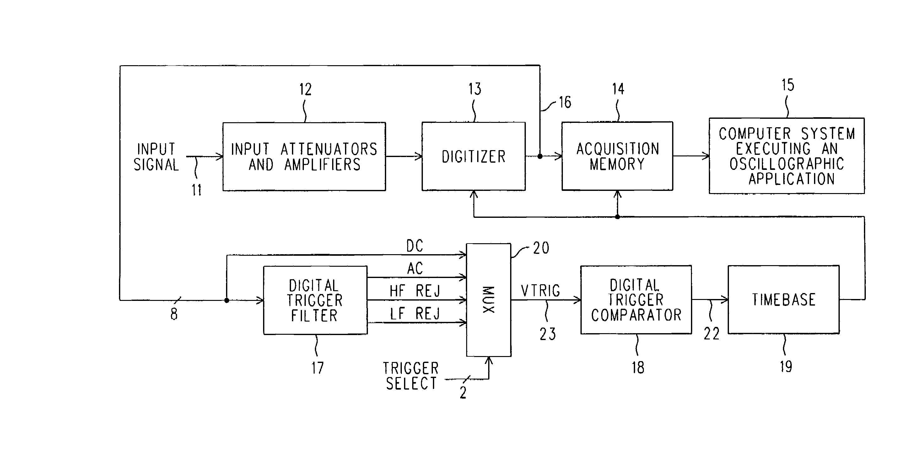
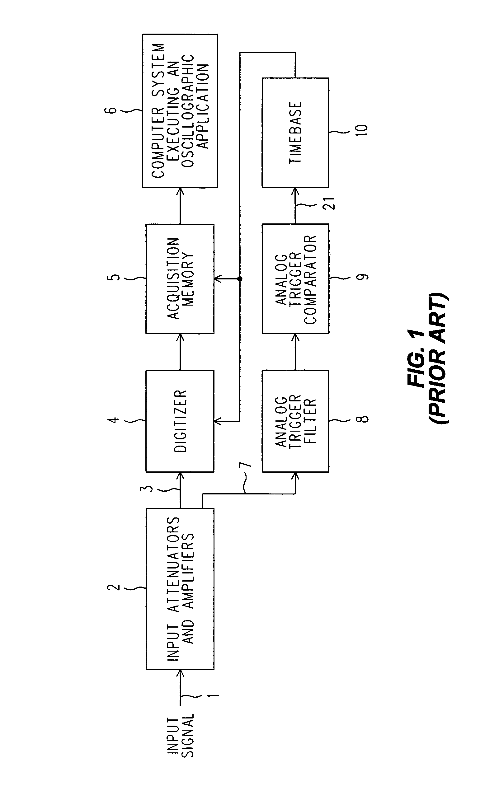
[0012]Refer now to FIG. 1, wherein is shown a simplified block diagram of a prior art DSO architecture that uses a conventional Analog Trigger Filter. In particular, an Input Signal 1 in applied to various Input Attenuators and Amplifiers 2, where signal conditioning takes place. A Conditioned Input Signal 3, which will be a suitable replica of the Actual Input Signal 1, is applied to a Digitizer (or analog to digital converter) 4 whose output is a series of digital words (preferably integers) of a suitable number of bits, say eight or ten, depending upon the vertical resolution the DSO is to have. The series of digital words is applied to an Acquisition Memory 5 that stores them internally as an Acquisition Record (not shown).

[0013]A Computer System 6 executes an Oscillographic Application that implements the majority of the control settings for the ‘scope, and interprets the Acquisition Record in light of those control settings. It then prepares a displayed trace with suitable ann...


PUM


Abstract

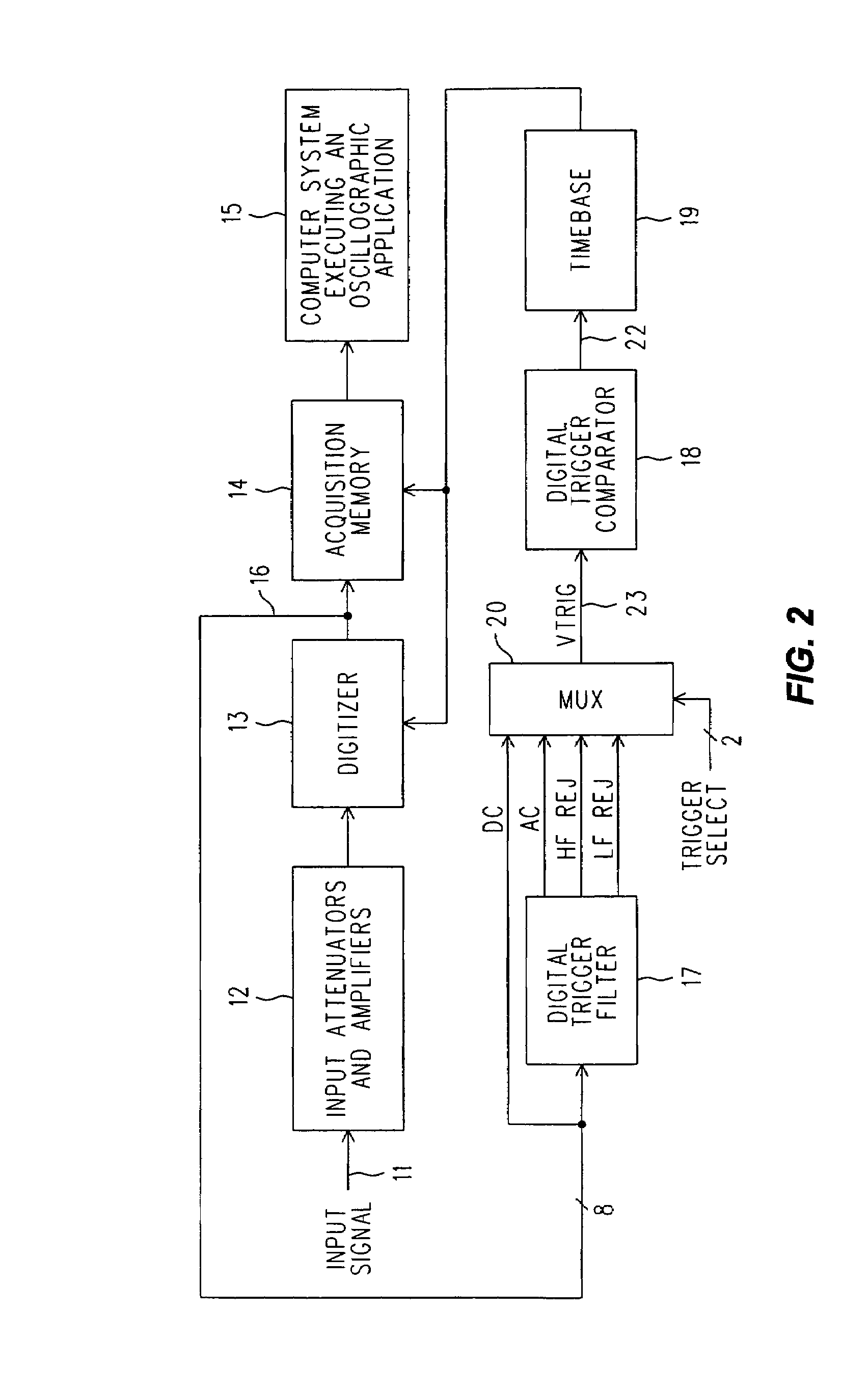
A real time DSO is equipped with a Digital Trigger Filter that performs high frequency rejection, low frequency rejection, AC and DC triggering. The Digital Trigger Filter includes first and second digitally implemented IIR (Infinite Input Response) Filters. A digitized Conditioned Input Signal is applied to the first IIR Filter. It has taps that provide the Trigger Signal outputs needed for high and low frequency rejection. The high frequency rejection output of the first ER Filter is essentially a low pass output (3 dB down at 50 KHz) and is also used as the digital input to the second IIR Filter, whose output is a much more aggressive suppression of high frequencies (3 dB down at 50 Hz). The AC Trigger Signal output is produced by subtracting the output of the second IIR filter from the original input to the entire Digital Trigger Filter, and the DC Trigger Signal output is simply the same as that original input. A MUX selects which Trigger Signal is applied to a Digital Trigger Comparator.

Description

BACKGROUND OF THE INVENTION[0001]DSOs (Digital Sampling Oscilloscopes) can be divided into two broad classifications: those that operate using ‘real time’ and those that operate using ‘equivalent time.’ A real time DSO takes consecutive samples at a rate high enough to meet Nyquist criteria for even ‘single shot’ events that contain frequency components up to the bandwidth of the ‘scope. And although a real time DSO will operate perfectly fine with repetitive inputs, there is no requirement that the input be repetitive to achieve full bandwidth. An equivalent time DSO cannot sample at the Nyquist rate, and relies upon the repetitive nature of the input to accumulate a replica of the input by sampling at a much lower rate, but at successively further locations along the input waveform, relative to a selected location identified by a trigger event.[0002]Today, virtually all oscilloscopes are triggered, in contrast to the original technique of simply synchronizing a free-running sweep ...

Claims


Application Information

Patent Timeline
Patent Type & Authority Patents(United States)
IPC IPC(8): G06F19/00
CPCG01R13/0254
Inventor WELLER, DENNIS J.
Owner KEYSIGHT TECH
Learn More