Motion detection for interlaced video

a technology of interlaced video and motion detection, which is applied in the field of interlaced video motion detection, can solve the problems of poor conversion performance, high vertical frequency twitter effect for pictures, and spatial interpolation does not fully utilize the achievable vertical-temporal (v-t) bandwidth

Active Publication Date: 2008-03-13
TEXAS INSTR INC
View PDF13 Cites 27 Cited by
  • Summary
  • Abstract
  • Description
  • Claims
  • Application Information

AI Technical Summary

Benefits of technology

[0027] The present invention provides a motion detection method and system useful in motion-adaptive de-interlacing which includes a variance-adaptive temporal IIR filtering of a motion measure.

Problems solved by technology

However, for a video display that can support a refresh rate high enough so that flicker is not perceivable, progressive scanning is preferable, since interlacing reduces the vertical display resolution and causes twitter effects for pictures with high vertical frequency.
The traditional spatial, temporal, and spatial-temporal interpolation schemes usually lead to poor conversion performance.
The spatial interpolation does not fully utilize the achievable vertical-temporal (V-T) bandwidth in filtering because it ignores the temporal spectrum, which reduces the vertical resolution.
The temporal interpolation, however, causes artifacts such as jaggy and feather effects when motion is present.
Although the spatial-temporal interpolation can fully utilize the V-T spectrum, it cannot handle motion scenes well.
However, this type of technique is of much higher complexity in implementation.
However, it is impossible to take the frame difference for interlaced sequences because pixels from consecutive fields do not have the same spatial locations.
The problem arising from two-field motion detection is that, without perfect reconstruction, there will be some errors inherent in the interpolation step.
These errors can make vertical details in the picture appear as moving even if it is static.
Thus, the interpolation may be done incorrectly and the resultant absolute difference between the interpolated pixel and its corresponding pixel in the previous field will not be an appropriate measure of motion.
This error leads to a significant number of false-detections.
As a result, more regions of the video sequence will be de-interlaced spatially than necessary, resulting in lower quality.
The drawback of two-field motion detection is due to the interpolation, which is not accurate.
While two-field motion detection results in many false positives (detection of motion when none is present), three-field motion detection results in many false negatives (failure to detect when motion is actually present) because it is unable to detect fast-moving regions.
The mis-detection caused by two- and three-field methods is the insufficient detection of information due to only one set of comparisons.
While this method has better performance than three-field motion detection, it can still miss detections.
The error usually happens when the motion detector designates a moving region as stationary.
This will result in no motion detected, but the frame actually changes a lot.
This method improves upon four-field motion detection by reducing the number of missed motion detections, but the tradeoff is that one more field storage is needed.
While this method does have the best performance of all the four methods discussed, it is still possible that some combination of frames can cause the motion detection method to miss areas of very fast and periodic motion.
For example, a sequence of fields with some region that flickers between two images once every field over a five-field duration will cause such problems.
These types of motion detection methods can only compare even fields with even fields or odd fields with odd fields.
Consequently, the flickers at such frame rate cannot possibly be detected.
The only type of motion detection that could detect this kind of flickers is a two-field based scheme, which has poor performance for the reasons mentioned previously in this section.
The problem is that eventually it becomes unreasonable to look so far into the future or past.
Additionally, the storage size requirement makes it impractical to do that.
While motion adaptive methods do perform very well in general, it is still possible for a combination of frames to cause the motion detector's failure.
As discussed above, the techniques of motion detection is a key component in de-interlacing system and each technique above has its weakness.

Method used


Image

  • Motion detection for interlaced video
  • Motion detection for interlaced video
  • Motion detection for interlaced video

Examples


Embodiment Construction

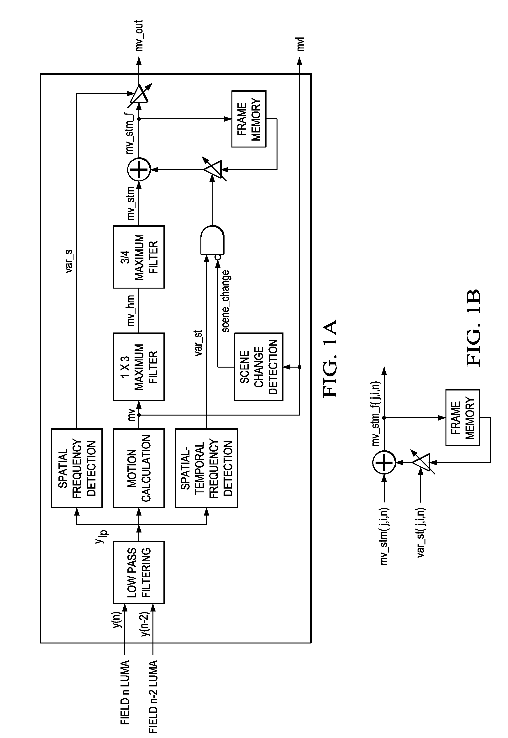
[0033] The block diagram of a preferred embodiment motion detector is shown in FIG. 1A. The inputs to the system are luma signals (i.e., Y of YCbCr pixel color) from two neighboring fields with the same parity (two odd fields or two even fields). The outputs are the detected measures of motion (“mv” for motion value). Note that there are different versions of motion outputs, which can be used at different applications. For example, the output, mv1, can be used for temporal noise reduction applications, in which motion should only account for the difference of pixels from the two neighboring fields with the same parity. However, for the applications of de-interlacing, as discussed above, motion detection that only accounts for two fields very likely results in misdetection (false negative), and thus spatial and temporal maximum filtering is usually needed. The output, mv_out, can then serve for this purpose.

[0034] Preferred embodiment systems such as TV phones, PDAs, notebook comput...


PUM


Abstract

Motion detection in interlaced video fields, as useful in de-interlacing, includes spatial-temporal maximum filtering, temporal IIR filtering dependent upon spatial-temporal variance, and spatial variance dependent moving-still interpolation blending factor.

Description

CROSS-REFERENCE TO RELATED APPLICATIONS [0001] This application claims priority from and incorporates by reference provisional application No. 60 / 823,790, filed Sep. 7, 2006. The following co-assigned copending patent application discloses related subject matter: Application Ser. No. 11 / 550,100, filed Oct. 17, 2006.BACKGROUND [0002] The present invention relates to digital video signal processing, and more particularly to interlace-to-progressive conversion. [0003] For moving picture systems, interlaced video format is widely used to reduce data rate. That is, each image frame consists of two fields, each of which contains samples of either the even numbered (top field) or the odd numbered (bottom field) lines of the image. In interlaced scan, fields are scanned and displayed sequentially, as shown for a 5×5 block of pixels in FIG. 5A. By taking advantage of the time it takes for an image to fade on a CRT, interlaced video gives the impression of double the actual refresh rate, help...

Claims


Application Information

Patent Timeline
Patent Type & Authority Applications(United States)
IPC IPC(8): H04N7/01
CPCG06T3/4084G06T7/2053H04N5/144H04N7/0142H04N7/0135H04N7/0137H04N7/012G06T7/254
Inventor ZHAI, FANCHANG, WEIDER PETER
Owner TEXAS INSTR INC
Why Eureka
Try Eureka