Method for manufacturing stent-grafts

a manufacturing method and stent technology, applied in the field of sewing machines, can solve the problems of high time and cost associated with attaching these sutures, high cost of assuring the quality of every stitch, and patient's health can be particularly serious, so as to increase the friction acting on the second thread

Inactive Publication Date: 2006-07-11
ANSON MEDICAL LTD
View PDF16 Cites 19 Cited by
  • Summary
  • Abstract
  • Description
  • Claims
  • Application Information

AI Technical Summary

Benefits of technology

[0017]The relative positioning of the needle and the bobbin allows the stitches to be made in a more confined environment than is possible with a conventional sewing machine, thereby allowing stitches to be made in the wall of relatively small diameter tubular grafts.
[0067]In a eleventh aspect of the present invention, therefore, there is provided apparatus for attaching wire (preferably a marker wire) to the wall of a tubular medical implant circumferentially around the implant and longitudinally along the implant, comprising a support for the implant, a needle to drive a first thread through the wall and into the bore of the implant, a bobbin for carrying a second thread through an open end of the implant into said bore in order to form a stitch in combination with the first thread to attach the wire to the implant wall, and a tube through which the wire is fed in order to be placed on the implant in the correct position prior to attachment to the implant, wherein the said tube is adapted to move from a first position in which it is perpendicular to the longitudinal axis of the implant to a second position in which it is parallel to said axis, to facilitate positioning of the wire on the implant. Preferably, the tube can be positioned to feed wire adjacent to the needle from any direction around the axis of the needle. Pinch rollers may be provided to feed said wire down said tube.

Problems solved by technology

Some designs employ many hundreds or thousands of sutures and the time and cost associated with attaching these sutures is high.
Additionally, the burden of assuring the quality of every stitch is expensive, while the implications of poor quality stitching in a device which is implanted into a patient can be particularly serious to the health of the patient.
In particular, the lengths, diameters, tapers, secondary tapers and the location of side-branches of stent-grafts are required to be tailor-made for each patient and this can take an unfeasible period of time when the stent-graft is made by hand.
This approach solves many of the issues associated with hand manufacturing but results in a seam and prevent some continuous structures from being designed.
This sewing machine could not be employed to stitch thread to the wall of a tubular graft, because the graft would not be sufficiently compliant to enable a folded section of graft to be sucked into the machine.
This means that movement of the needle independently of the shuttle is not possible for all degrees of freedom.
In particular, movement of the needle holder to pierce the needle through the wall of a tubular implant would inevitably result in a corresponding movement of the shuttle within the bore of the implant.
In practice, it would not be possible to manipulate the needle without causing the shuttle to impact the side walls of the implant, thereby risking damage to the implant.
Thus the needle could never penetrate the side wall of a tubular implant.

Method used


Image

  • Method for manufacturing stent-grafts
  • Method for manufacturing stent-grafts
  • Method for manufacturing stent-grafts

Examples


Embodiment Construction

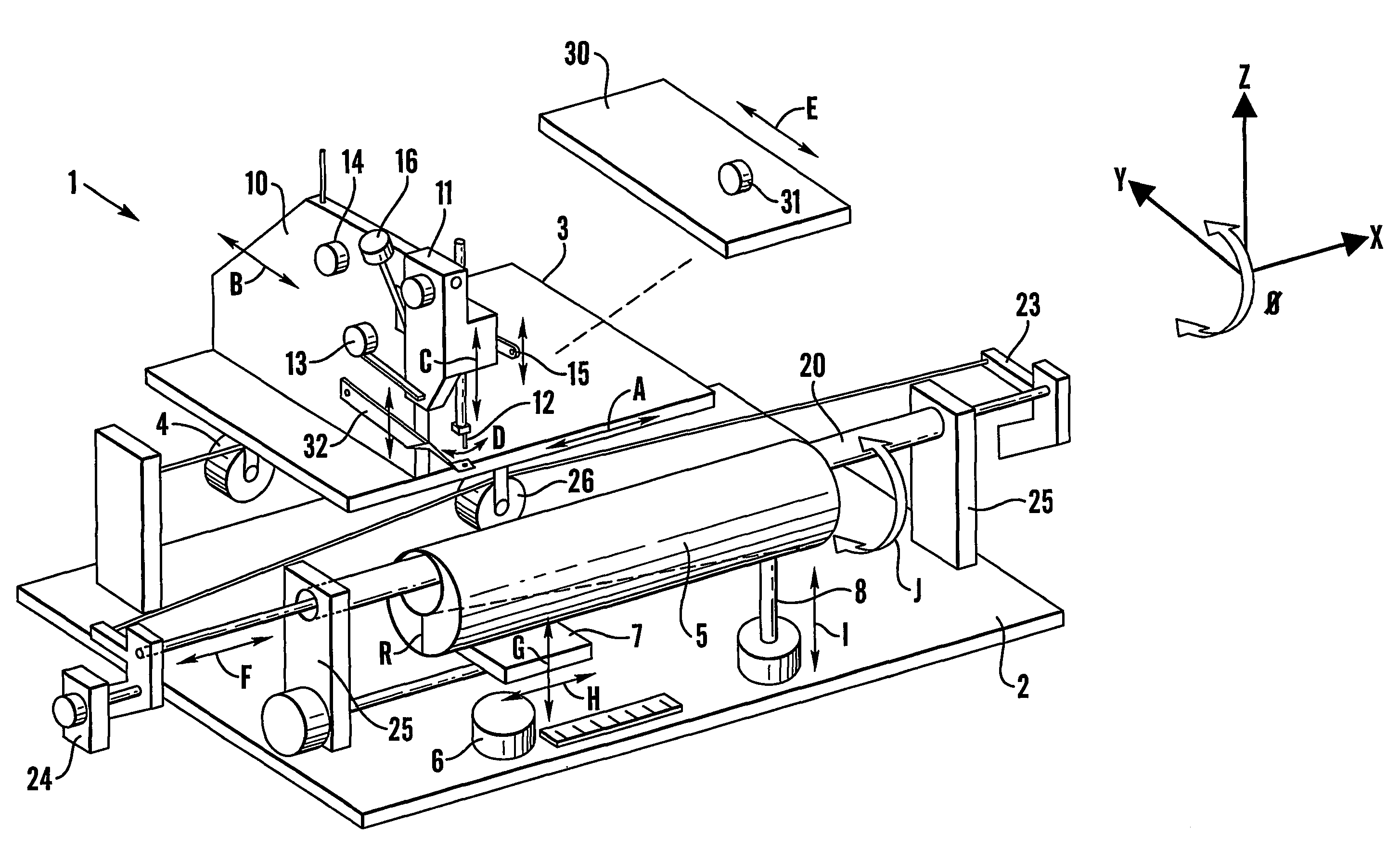
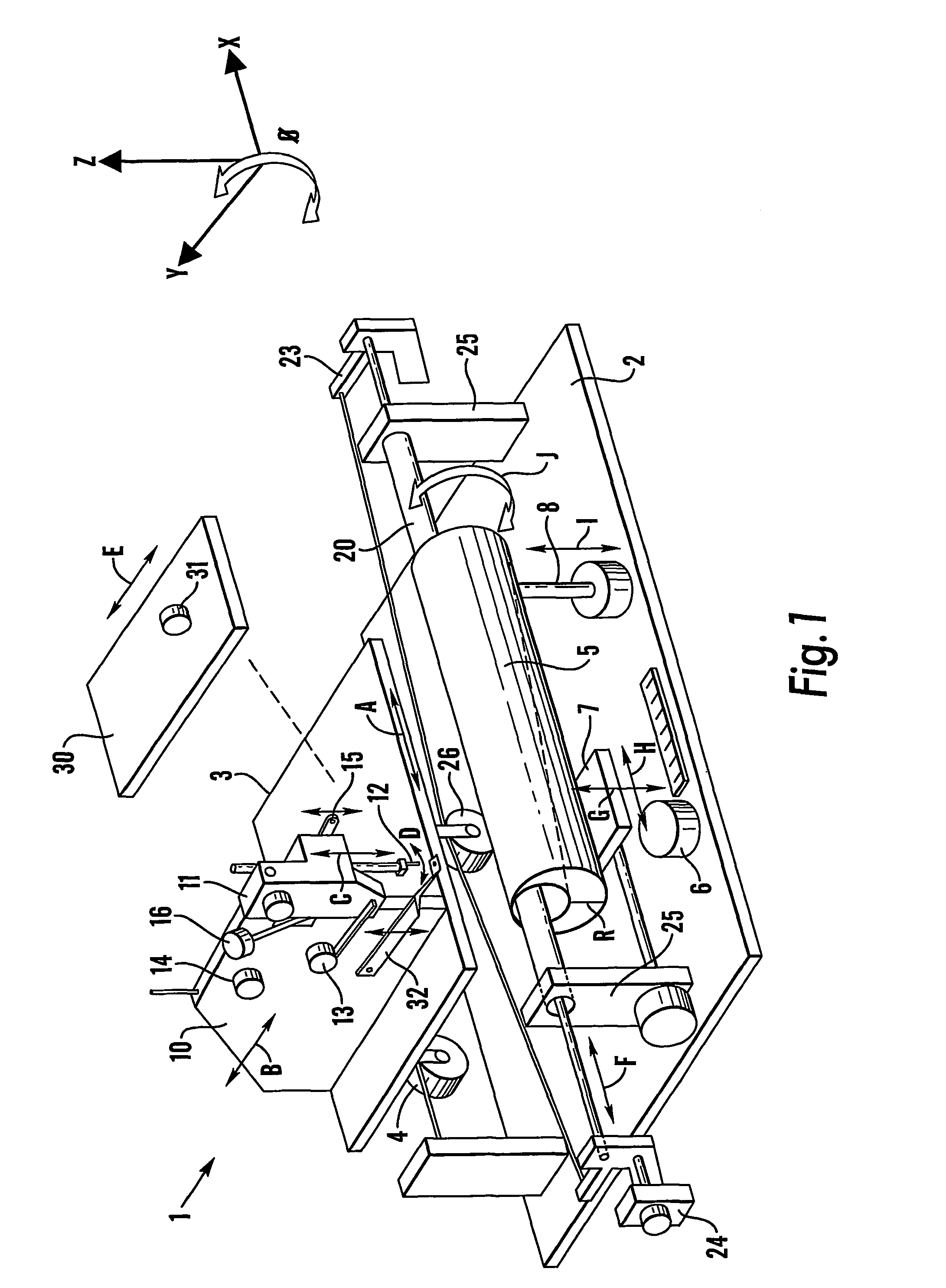
[0078]Turning to FIG. 1, sewing machine 1 comprises a base 2 having mounted thereon a sew arm 10, shuttle tube 20 and stent table 30.

[0079]Graft 5 is held by a pair of grips (not shown) at either end of graft 5 with shuttle tube 20 passing through the lumen of graft 5 and being supported at either end by shuttle tube supports 25 which are also mounted on base 2.

[0080]Sew arm 10 is mounted on carriage 3 which is driven by carriage drive 4 in directions parallel and perpendicular to shuttle tube 20 (as indicated by arrows A and B respectively) so that sew arm 10 can be positioned as required relative to graft 5.

[0081]Sew arm 10 comprises a needle head 11 which projects over the edge of carriage 3 and which has needle 12 which can be driven up and down relative to graft 5 (as indicated by arrow C) and side to side (so-called “needle wobble”) by needle wobble drive (as indicated by arrow D). Needle head 11 controls the deployment of the top thread (not shown), which passes from a spool ...


PUM


Abstract

A sewing machine is provided which is capable of sewing reinforcing wire to tubular grafts in order to form stent grafts. A bobbin (which may be seated in a shuttle) carries a bottom thread through the bore of the tubular graft and forms a stitch in combination with a top thread carried on a needle which pierces the graft wall.

Description

FIELD OF THE INVENTION[0001]This application relates to a sewing machine and in particular to a sewing machine for use in the construction of vascular stent-grafts.BACKGROUND OF THE INVENTION[0002]Stent-grafts are tubular constructions for use inside blood vessels. They generally comprise two components: a quasi blood-tight tube that is usually formed of textile or membranous material, and a reinforcing structure which is usually made of wire or other filamentous metallic material.[0003]The tubular graft component is usually made from woven polyester fabric, although a few designs employ PTFE membranes. The graft is supported on metallic rings which are generally formed from wire but are occasionally cut from metal tube by means of laser cutting or similar means. When attached to the graft, the metal rings can define a single plane at an angle to the axis of the graft, the rings can be corrugated so that they define the surface of a short cylinder on the surface of the graft, or the...

Claims


Application Information

Patent Timeline
Patent Type & Authority Patents(United States)
IPC IPC(8): D05B23/00A61B17/062A61F2/07D05B57/12
CPCD05B57/12D05B23/00A61F2/07A61F2002/075A61F2/06A61F2/86A61F2/95
Inventor PHILLIPS, PETERWOODWARD, ADRIAN MICHAELHALKET, ANDREW RICHARD BUCHANANBEATON, GAILPERKS, CARL JOHNANGEL, CLIVE GRAHAMFROST, TIMOTHY FAULKNER
Owner ANSON MEDICAL LTD
Why Eureka
Try Eureka