Device and method for remote maintenance of an elevator

a technology for remote maintenance and monitoring of elevators, applied in the direction of elevators, instruments, computer control, etc., can solve the problems of inconvenient and expensive adaptation of remote maintenance functions, high device cost, and possible cost-intensive effects of devices, and achieve the effect of convenient mounting and demounting

Active Publication Date: 2006-07-11
INVENTIO AG
View PDF16 Cites 91 Cited by
  • Summary
  • Abstract
  • Description
  • Claims
  • Application Information

AI Technical Summary

Benefits of technology

[0018]Advantages resulting therefrom consist in that the device can be easily mounted and demounted, so that the elevator installation is operable with or without remote maintenance funct...

Problems solved by technology

In this manner, elevator installations equipped with an elevator control individual to each elevator, together with modem extension and central service center have proved themselves, yet due to their constructional and functional characteristics to the extent explained they are expensive in terms of devices and only a restricted selection of predefined reports can be transferred monodirectionally to the service center.
The maintenance of the individual elevator installations which are connected in the overall system with the service center and are disposed locally far apart from one another turns out to be cost intensive, since, in t...

Method used


Image

  • Device and method for remote maintenance of an elevator
  • Device and method for remote maintenance of an elevator
  • Device and method for remote maintenance of an elevator

Examples


first embodiment

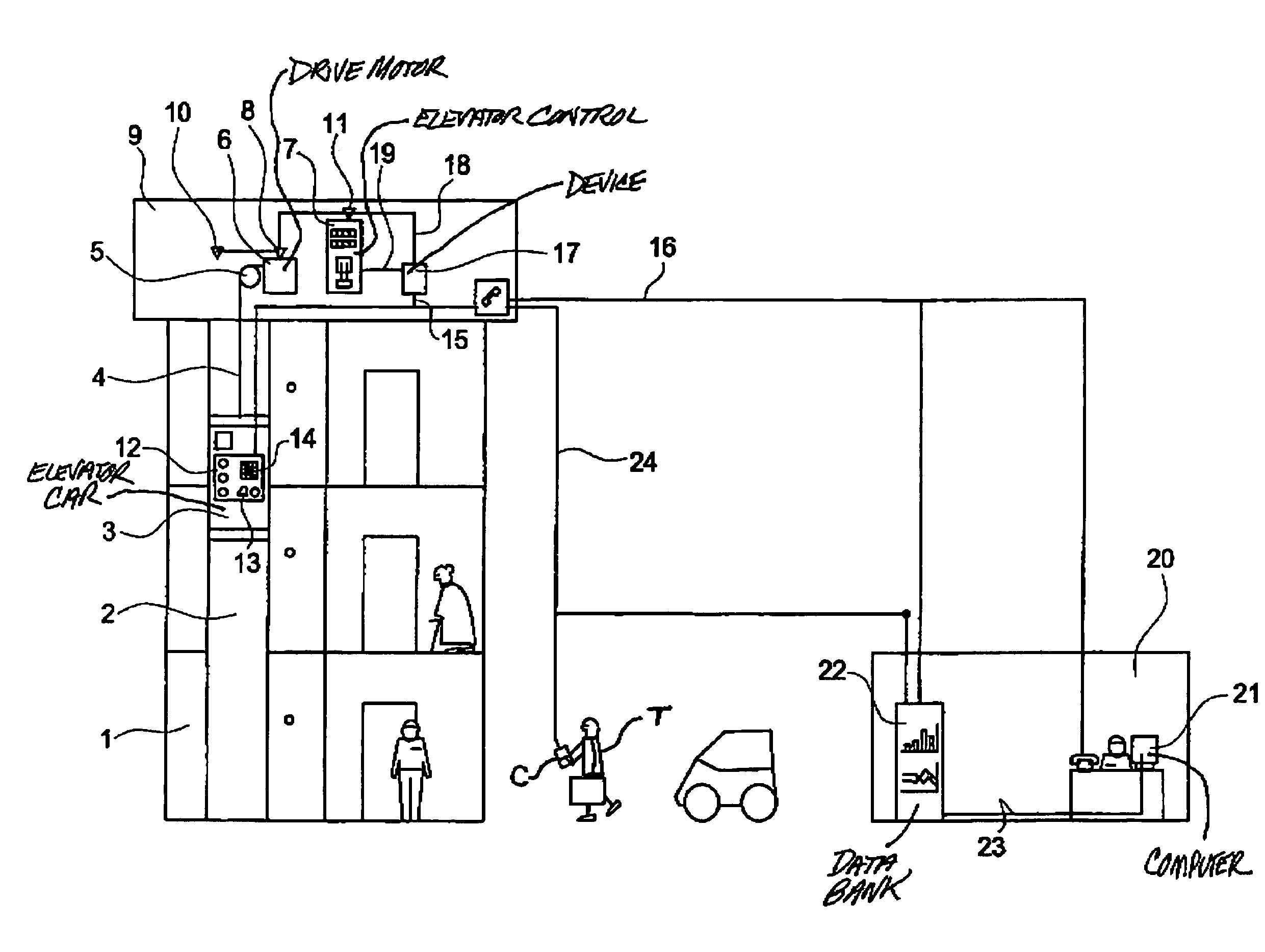
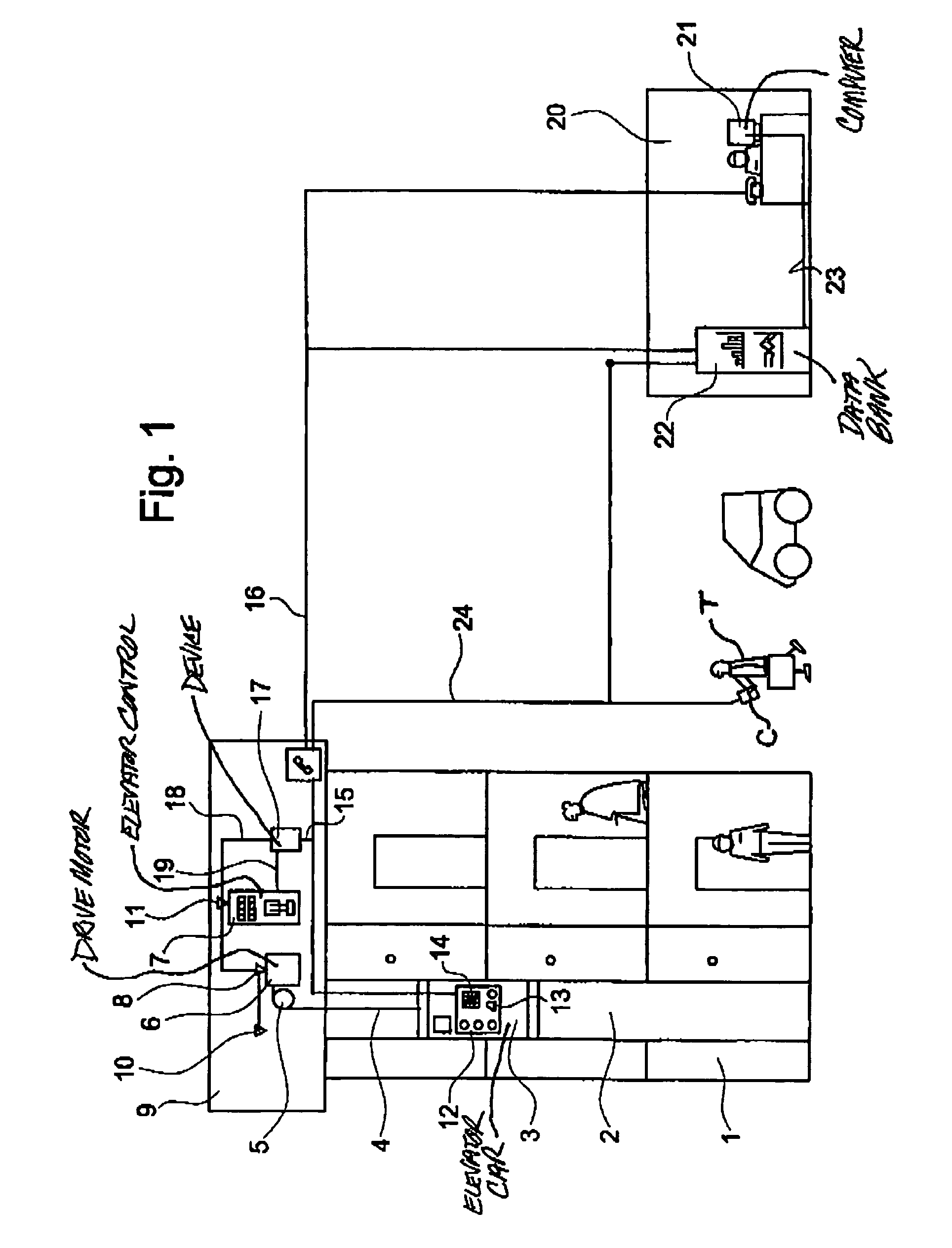
[0029]An elevator installation, which has an elevator car 3 movable in a shaft 2, is denoted by 1 in FIG. 1. The elevator installation 1 can be, as in this example of a first embodiment, a single elevator or also, however, an installation with several elevators, which are linked into a group in terms of control, in a building. The elevator car 3 is suspended at cables 4 guided over a drive pulley 5. The drive pulley 5 is set in motion by means of the drive motor 6, which is supplied with electrical energy by way of an elevator control 7. For monitoring the movement of the drive pulley 5 and thus the position of the elevator car 3 in the shaft 2 there is provided, for example, a position sensor 8. A temperature sensor 10 is also disposed in a machine room 9, for example at the drive motor 6. A current sensor 11 measures, for example, a current flowing in the elevator control 7. A car control panel 12, by way of which the travel destinations are registered, is arranged in the elevator...

third embodiment

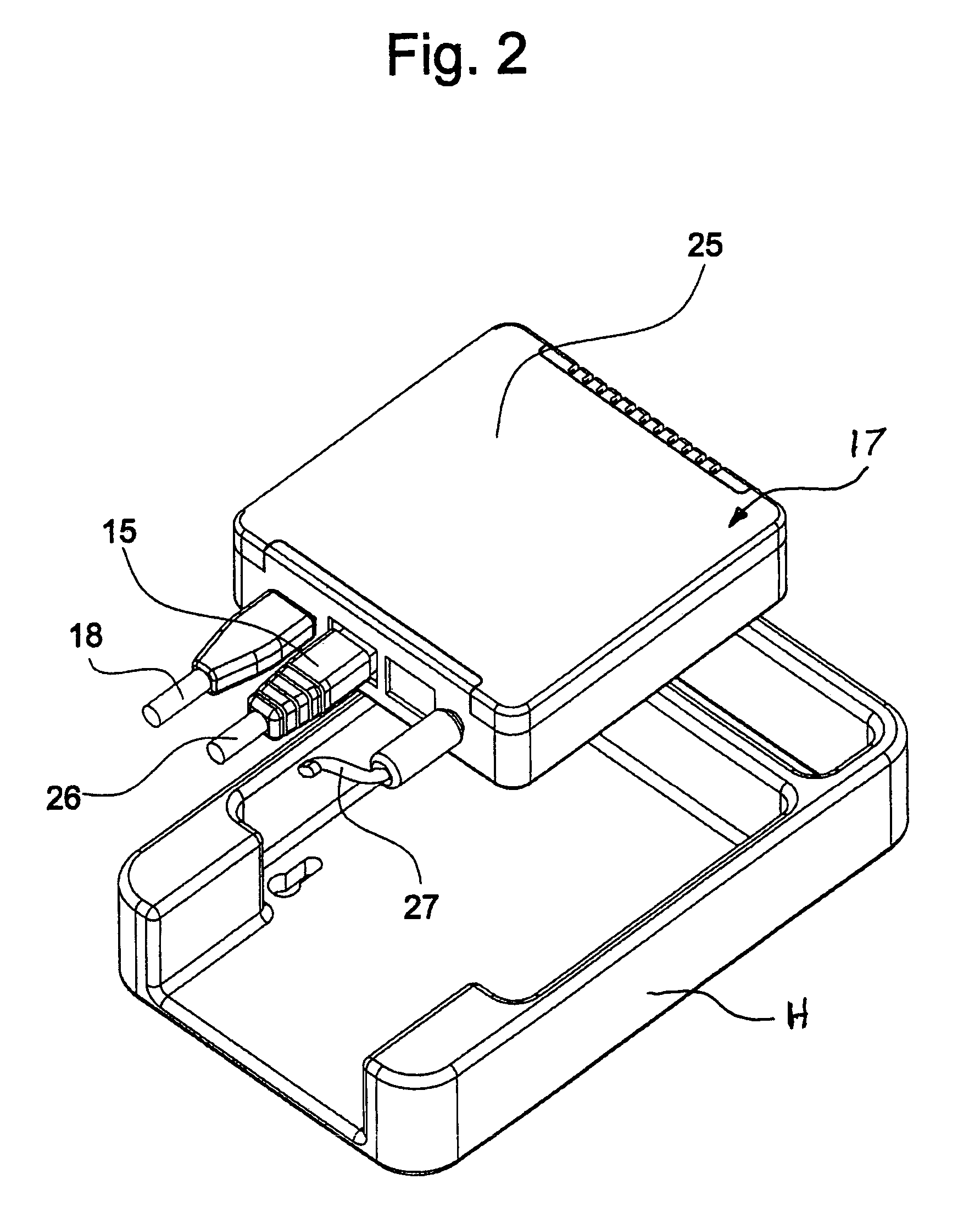
[0059]FIG. 6 is an exploded illustration of a modular form third embodiment of the device 17. A plug frame 45 acts as cover. The processor (CPU, Central Processing Unit) and the difference serial interfaces, such as the universal serial bus (USB), the plug RS232, the modem, the Ethernet connection, the line manager telephone (LU) and the LON are constructed as separate, independent modules 46 and inserted into separate bays in the plug frame 45. Communication between these separate modules 46 is looked after by a back panel 47, which panel is also pushed into the plug frame 45 and has several plug pins in order to connect with the plugs of the modules 46. A serial communication by a bus between the modules 46, which is distinguished by being particularly flexible and free in configuration, is achieved by the back panel 47. At the same time, the current supply by means of separate contacts is integrated in the plug strip.

[0060]The modular construction of the device 17 shown in FIG. 6...


PUM


Abstract

A device for remote maintenance and monitoring of an elevator installation has at least one input for the detection of first signals from an elevator control and/or from a sensor, at least one output of second signals to a telecommunications network and a processor and a data memory. A set of remote maintenance functions is stored in the data memory and each of these remote maintenance functions is selectively activatable.

Description

BACKGROUND OF THE INVENTION[0001]The present invention relates to an elevator and a method for remote maintenance and monitoring of an elevator installation.[0002]For operational control there is associated with each elevator installation an elevator control with which sensors and actuators, for example control, actuating and setting elements of the elevator installation, are connected. A microprocessor of the local elevator control reads the input signals and switches the output signals in correspondence with the provided control program or regulating program. The processing of the signals and the data which are stored in the elevator control and describe the elevator installation, for example floor number, drive type, etc., is carried out in a microprocessor in situ at the elevator installation.[0003]Elevator installations, the elevators of which are equipped with, apart from a conventional elevator control, additionally a modem for remote maintenance, are shown in the patent spec...

Claims


Application Information

Patent Timeline
IPC IPC(8): B66B1/34B66B5/00B66B3/00H01H1/00
CPCB66B5/0025B66B5/0087B66B19/007
Inventor WEINBERGER, KARLSCHUSTER, KILIAN
Owner INVENTIO AG
Why Eureka
Try Eureka