Aircraft structure fatigue alleviation

a technology for aircraft and structure, applied in aircraft components, aircraft control, fuel tanks of power plants, etc., can solve the problems of micro cracks, aircraft may be scrapped or require major repair, and aircraft may be scrapped or scrapped, so as to achieve the effect of improving fatigue alleviation

Inactive Publication Date: 2006-07-11
AIRBUS OPERATIONS LTD
View PDF5 Cites 17 Cited by
  • Summary
  • Abstract
  • Description
  • Claims
  • Application Information

AI Technical Summary

Benefits of technology

[0011]The present invention seeks to alleviate these problems and provide improved fatigue alleviation during the GAG cycle.

Problems solved by technology

A limiting factor in the design of such aircraft is the strength of the materials used, including those of the wing.
The aircraft may then be scrapped or require major repair.
Secondly during all stages of the ground-air-ground (GAG) cycle, the wing is subjected cyclic loading conditions which cumulatively, over time, lead to the formation and then propagation of micro cracks and may ultimately appear as detectable cracks which require repair or maintenance to the aircraft.
Unfortunately this also maximises damage to the wing during pre-flight taxiing and the take-off run.

Method used


Image

  • Aircraft structure fatigue alleviation
  • Aircraft structure fatigue alleviation

Examples


Embodiment Construction

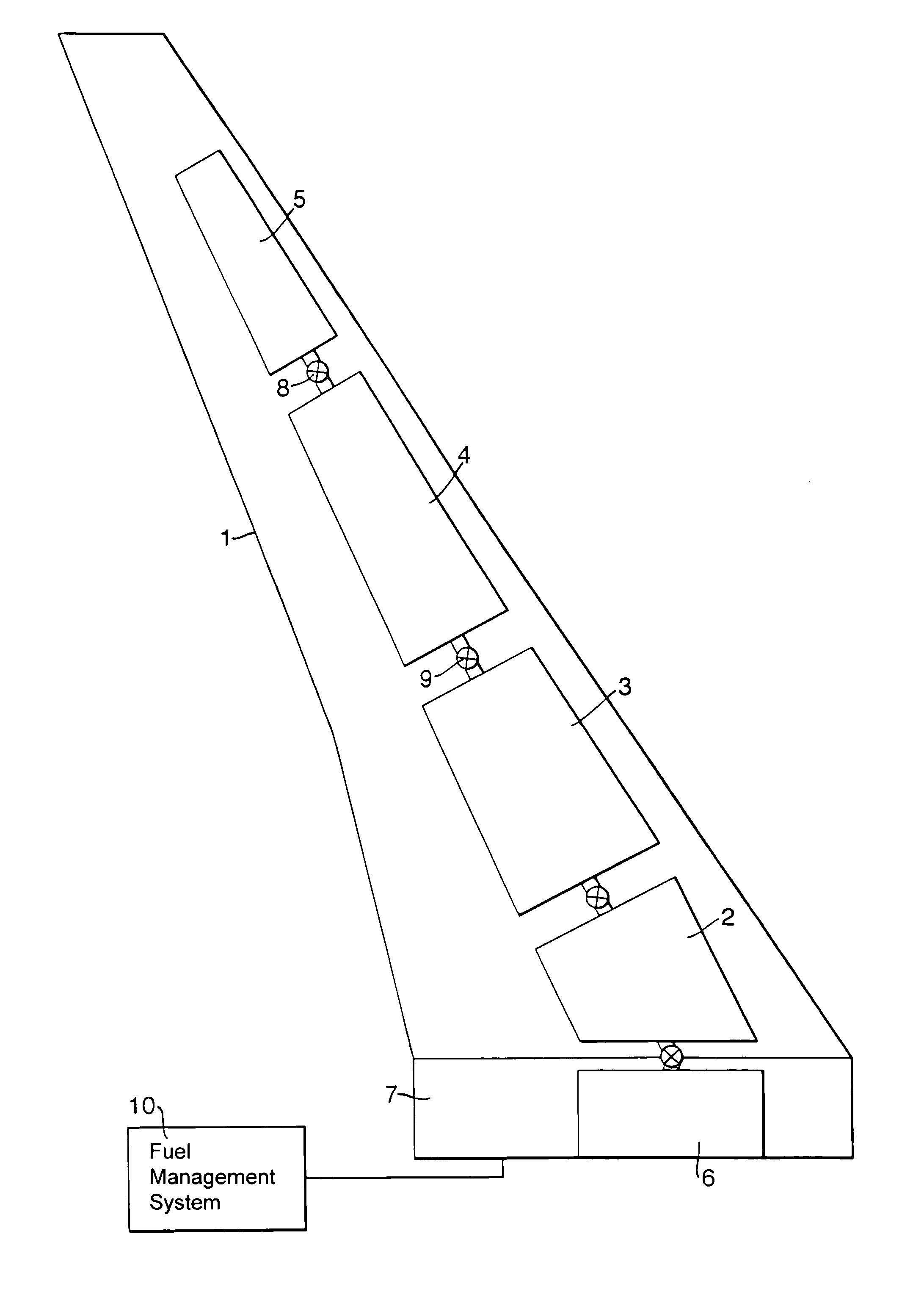
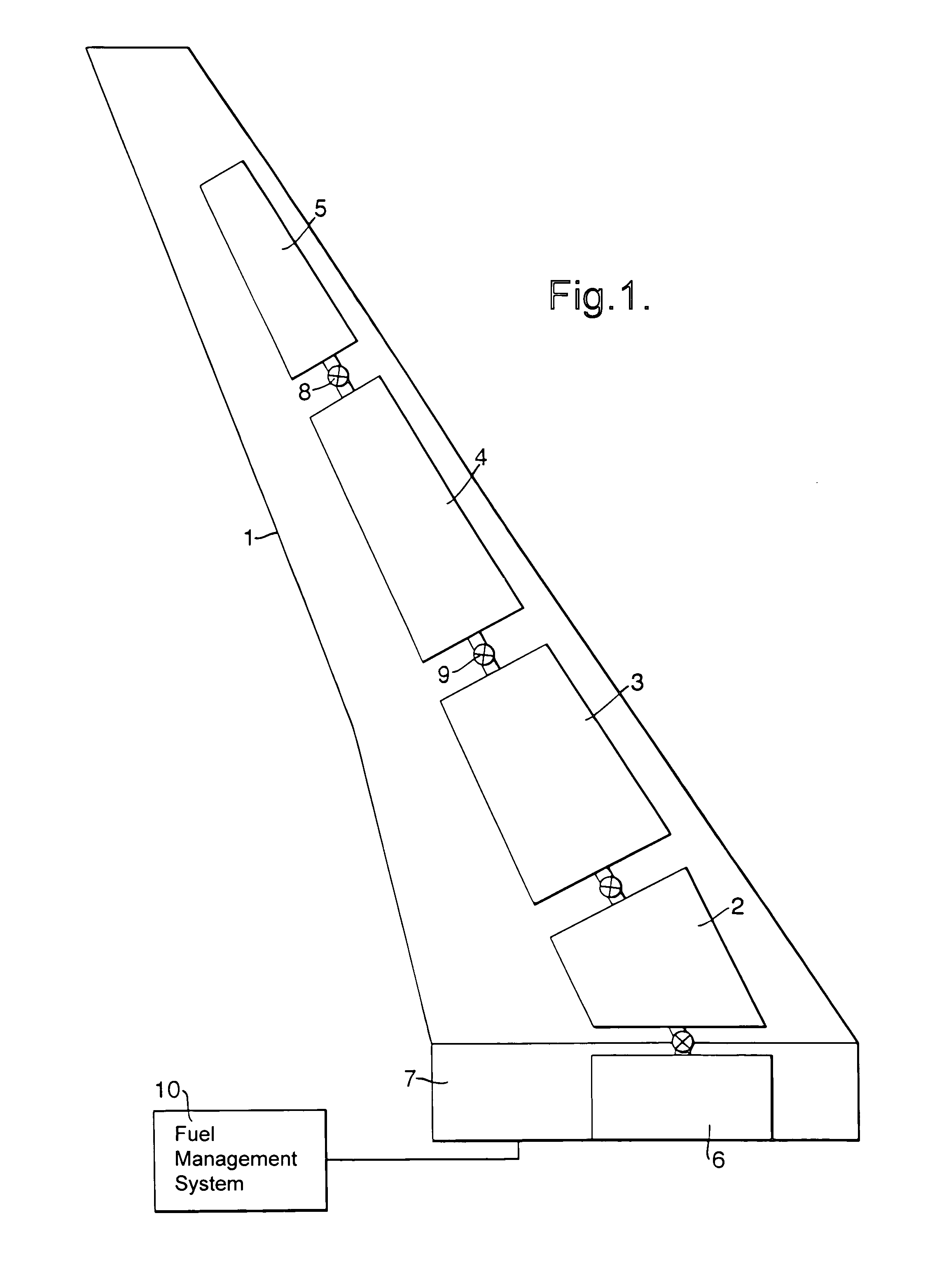
[0035]The drawing shows the distribution of tanks between the fuselage and one wing of an aircraft, the reader will appreciate that the principle can be extended to the second wing of the aircraft and that more or fewer tanks may be used, taking account of the size and fuel requirements of the aircraft in question. The wing (1) comprises 4 fuel tanks, an inner engine feed tank (2), an inner transfer tank (3), an outer engine feed tank (4) and an outer transfer tank (5). A further fuel tank, the centre tank (6) is located in the fuselage (7). Each of the tanks is connected to a fuel line (8) in which, between it and each tank, is located a two way valve (9). The fuel management system (10) coordinates the following fuel transfer operation during the GAG cycle.

[0036]Prior to taxi and in the run up to take off, each of the engine feed tanks (2, 4) retains a minimum safe level of fuel sufficient to operate the engines (not shown). Depending on the volume of fuel carried, the remaining f...


PUM


Abstract

A fuel transfer apparatus for an aircraft comprises:
    • two or more fuel tanks (2,3,4,5,6) arranged in an inboard to outboard alignment, at least one being situated in the wing (1) of the aircraft,
    • means for transferring fuel between the tanks (8, 9), and
    • a fuel management system (10) for controlling and monitoring the transfer of fuel between tanks
the fuel management system comprises;
  • means for receiving a first input signal that the aircraft has left the ground,
  • means for receiving a second input signal that the aircraft is approaching its destination,
  • means for initiating the transfer of the fuel from a relatively inboard tank location to a relatively outboard tank location in response to the first input signal, and
  • means for initiating the transfer of the fuel from a relatively outboard tank location to a relatively inboard tank location in response to the second input signal.
  • Description

    [0001]This application is the US national phase of international application PCT / GB00 / 01998, filed in English on May 25, 2000 which designated the US. PCT / GB00 / 01998 claims priority to GB Application No. 9913032.0 filed Jun. 5, 1999. The entire contents of these applications are incorporatd herein by reference.BACKGROUND OF THE INVENTION[0002]1. Field of the Invention[0003]This invention relates to fatigue alleviation in aircraft during all phases of the ground-air-ground cycle (GAG).[0004]2. Discussion of Prior Art[0005]This invention relates to fatigue alleviation in aircraft during all phases of the ground-air-ground cycle (GAG).[0006]Due to an increased demand for international air travel and in air traffic generally, there is a recognised need to increase the size and efficiency of both passenger and transporter aircraft. Customers also desire the capability to fly long distances at economical cost. As well as the physical size of the aircraft itself, the engineer has to consid...

    Claims


    Application Information

    Patent Timeline
    Patent Type & Authority Patents(United States)
    IPC IPC(8): B64C17/10B64D37/00
    CPCB64C17/10B64D37/00Y02T50/44Y02T50/40
    Inventor TIGHE, DAVID JWILLIAMS, ANDREW D
    Owner AIRBUS OPERATIONS LTD
    Why Eureka
    Try Eureka