Adjustable overhead trouble light stand

a light stand and adjustment technology, applied in the field of illumination, can solve the problems of inability to adjust the height of the light stand, the object not in the direct illumination path may receive inadequate light for accurate sensory information to be gained in minimal time, and the general inadequate overhead or spot lighting, etc., to achieve convenient use, minimize manufacturing cost and complexity, and simplify the setup

Active Publication Date: 2006-07-11
KREMERS BERNARD J +1
View PDF10 Cites 52 Cited by
  • Summary
  • Abstract
  • Description
  • Claims
  • Application Information

AI Technical Summary

Benefits of technology

[0013]Exemplary embodiments of the present invention solve inadequacies of the prior art by providing a stand-supported light source which includes a combination of collapsing, telescopic and flexible joint couplings. For storage and shipping, a plurality of legs are collapsible to longitudinally parallel to the longitudinal axis of the base. Similarly, a telescopic arm is pivoted into a longitudinally parallel axis, and then telescopically retracted. In use, the telescopic arm may be extended through a range of positions, and pivoted out of parallel with the stand base longitudinal axis. The legs are pivoted and self locking at a limited range of motion, simplifying set-up. A special clamp accepts a standard trouble light, without inhibiting access to or use of the various electrical switches and outlets that might typically be found thereon.
[0014]A first object of the present invention is to enable a person to position the light source at substantially any position and angle, including components providing both rectilinear and radial adjustment from a ground level illumination to a substantial height. A second object of the invention is to provide a stand which is readily adaptable to a wide variety of light sources, and which does not block or interfere with features or components available thereon. Another object of the present invention is to enable the stand to be collapsed for compact storage and transport, while providing safe and stable use. A further object of the invention is to utilize common components, to minimize manufacturing cost and complexity. Yet another object of the present invention is to provide an adaptable and readily used light stand which can provide adequate reach and positioning for even the most difficult of locations.

Problems solved by technology

Insufficient illumination has been demonstrated through much research to result in errors of judgment, accidents, and loss of efficiency.
While these methods of illumination provide suitable lighting for objects which are in direct line with such light sources, any objects not in direct illumination path may receive inadequate light for accurate sensory information to be gained in minimal time.
Consequently, objects which are shadowed, such as may be found in fight places or in complex geometrical structures of machines or other such constructions, overhead or spot lighting is generally inadequate.
In more complex locations, even intense lighting such as daylight may be inadequate, since other objects may block enough light to prevent a persons from discerning shapes and objects quickly and efficiently.
Unfortunately, there are many environments and tasks where the hanging light may not be adequately positioned to produce the appropriate light, shadowing and contrast desired.
One common environment where this is a problem is in the assembly or repair of large and complex machines, such as automobile power trains.
Yet the space is very limited, and in some instances the components such as engine or exhaust manifold may be very hot and hazardous.
Consequently, with insufficient light, a mechanic may easily accidentally touch a searing hot component, or may poorly grasp and consequently drop a component.
The common hanger will illuminate some of the components, but there are many instances where a hanger is not available at the right position or the direction of illumination when the light is hung from a nearby hanger is inadequate.

Method used


Image

  • Adjustable overhead trouble light stand
  • Adjustable overhead trouble light stand
  • Adjustable overhead trouble light stand

Examples


Embodiment Construction

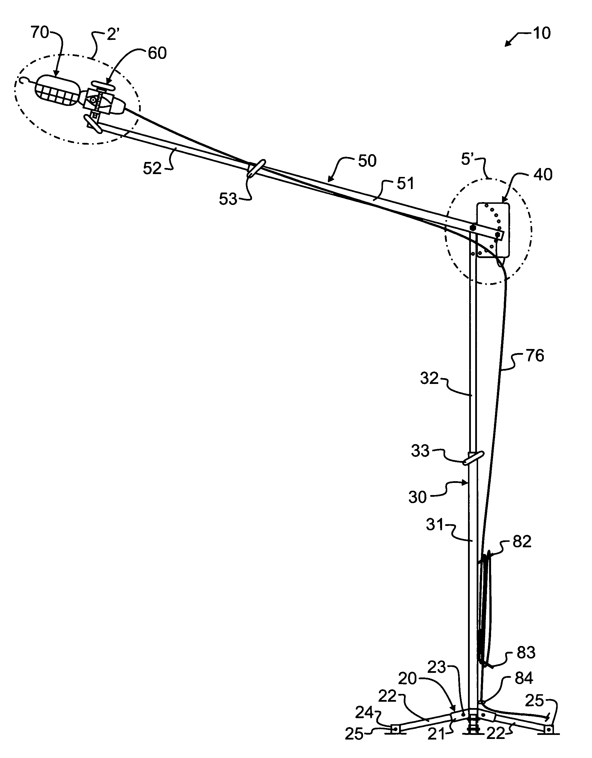
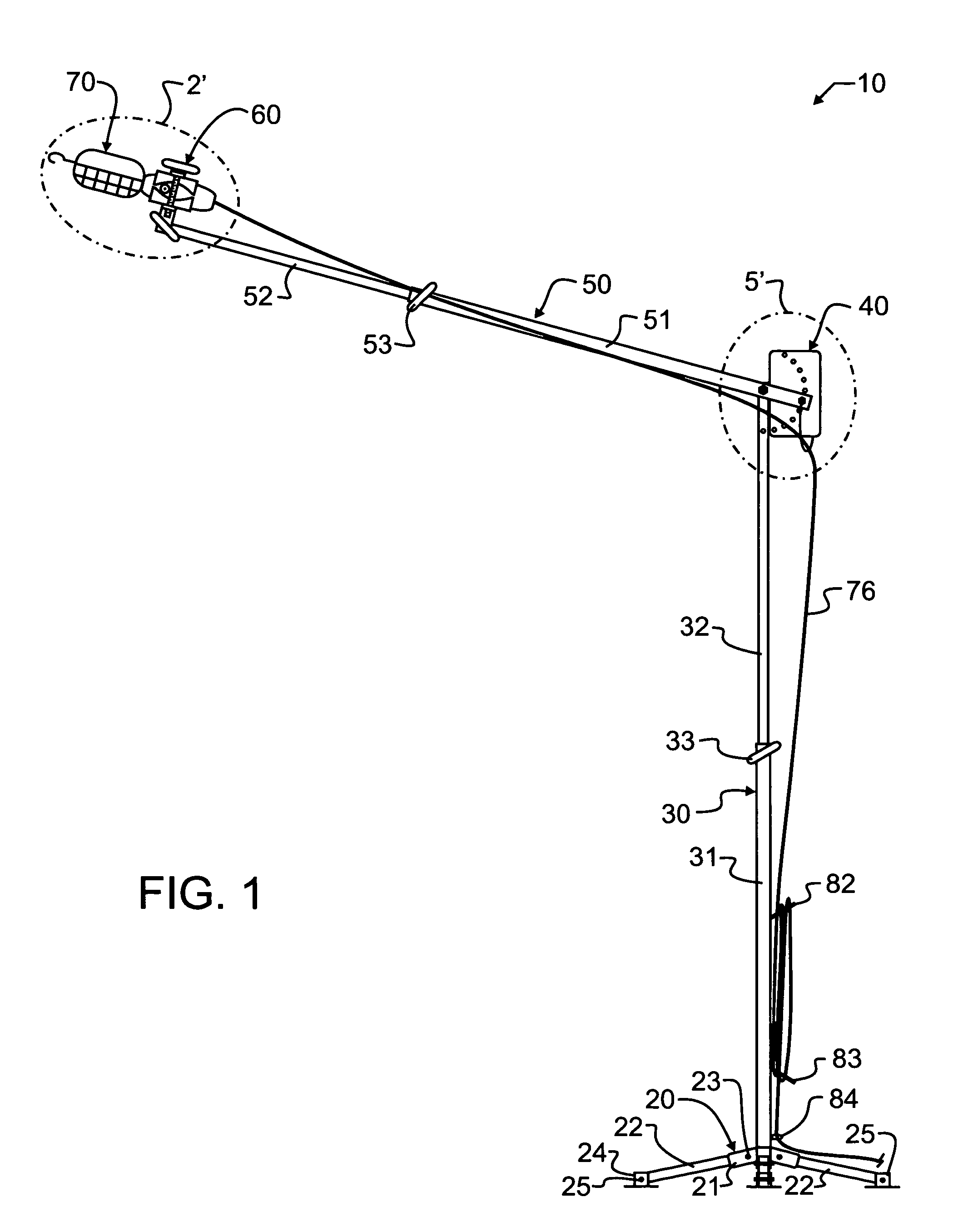
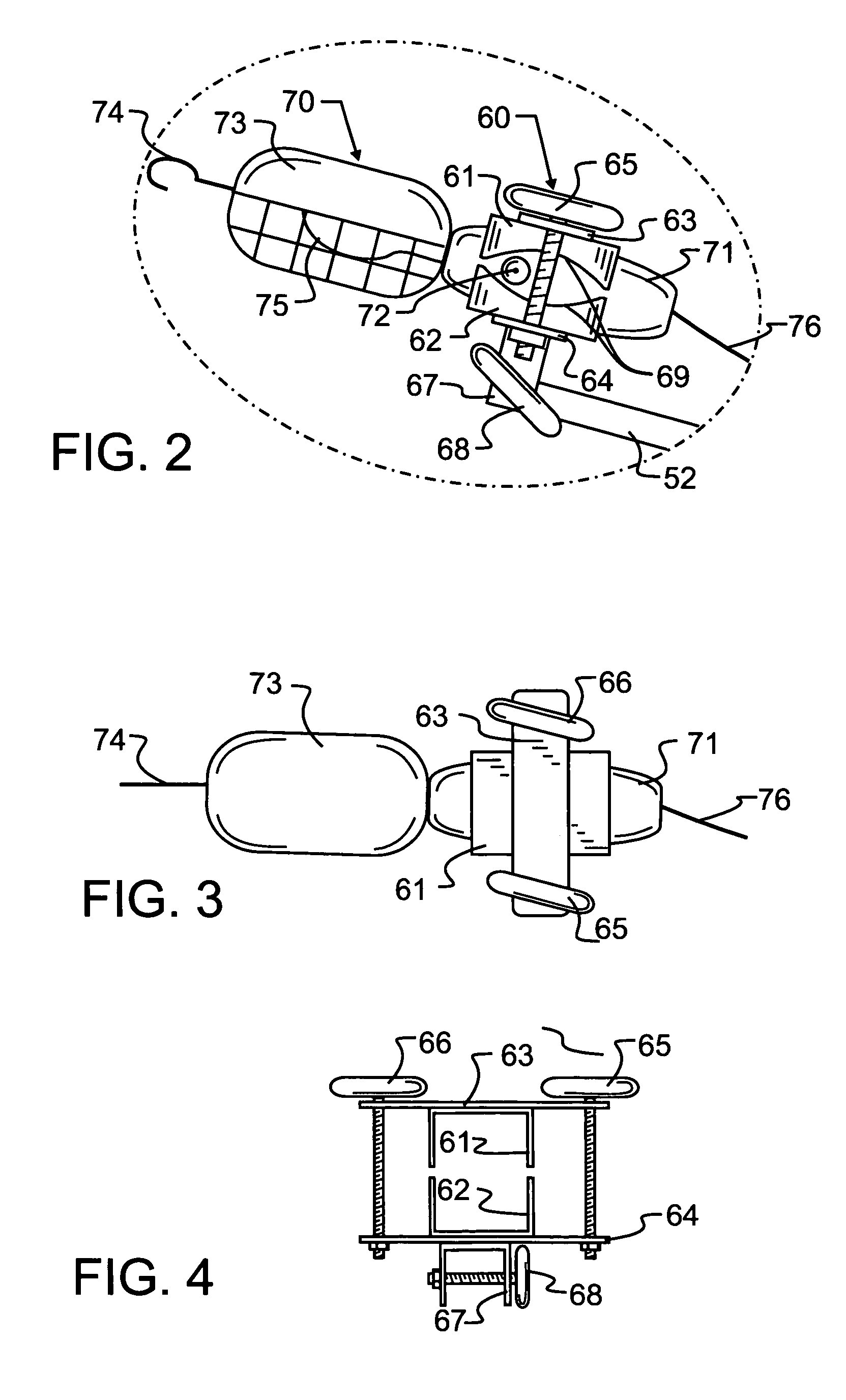
[0022]Manifested in the preferred embodiment stand-supported light source 10, the present invention combines collapsing, telescopic, pivotal and flexible joint couplings into a stand suitable for supporting diverse light sources. As illustrated generally in FIG. 1, preferred embodiment stand-supported light source 10 is comprised by seven major components, including collapsible base 20, telescopically extensible vertical standard 30, pivotal joint 40, telescopically extensible arm 50, clamp 60, light source 70, and electric cord supports 81–83. Ordinary components commonly used will be recognized and understood to be contemplated herein, for exemplary purposes but not limited thereto including such devices as washers of steel, polytetrafluoroethylene, polyethylene, polypropylene, nylon or the like. The use and selection of such ordinary components will be understood to be incorporated herein without specific discussion thereto.

[0023]Collapsible base 20 most preferably includes at le...


PUM


Abstract

A stand-supported light source includes a combination of collapsing, telescopic and flexible joint couplings. For storage and shipping, a plurality of legs are collapsible to become longitudinally parallel to the longitudinal axis of the base. A telescopic arm coupled to the stand may also be pivoted into a longitudinally parallel axis and then telescopically retracted, which results in a very compact configuration. In use, the telescopic arm may be extended through a range of positions, and may pivot out of parallel with the stand base longitudinal axis, permitting the light source to be located through a wide and precisely controlled range of motion. The legs are pivoted and self locking at a limited range of motion, simplifying set-up. A special clamp accepts a standard trouble light, without inhibiting access to or use of the various electrical switches and outlets that might typically be found on the trouble light. Different embodiments detail the pivot, clamp and various combinations.

Description

CROSS REFERENCE TO RELATED APPLICATIONS[0001]This application claims priority to U.S. provisional application Ser. No. 60 / 484,415 filed Jun. 30, 2003 of common title and inventorship, the contents which are incorporated herein by reference in entirety.BACKGROUND OF THE INVENTION[0002]1. Field of the Invention[0003]This invention pertains generally to the field of illumination, and more particularly to a trouble light stand which may be configured for overhead or underneath illumination from a virtually unlimited number of angles and with diverse work objects by simple manipulation of a few mechanical connectors.[0004]2. Description of the Related Art[0005]Human beings are capable of using the human intellect to make an amazing number of decisions and perform an equally amazing number of actions in very short time periods. Regardless of the decision or activity, the human intellect is dependent upon sensory information received through the five senses of sight, hearing, sound, touch,...

Claims


Application Information

Patent Timeline
Patent Type & Authority Patents(United States)
IPC IPC(8): F21S8/08
CPCF16M11/00F16M11/10F16M11/2021F16M11/28F21V21/26F21L14/02F21V21/06F21V21/145F21V21/22F16M2200/024
Inventor KREMERS, BERNARD J.KREMERS, CYNTHIA M.
Owner KREMERS BERNARD J
Why Eureka
Try Eureka